A6747
Aa
l
Aa.5
Fig.
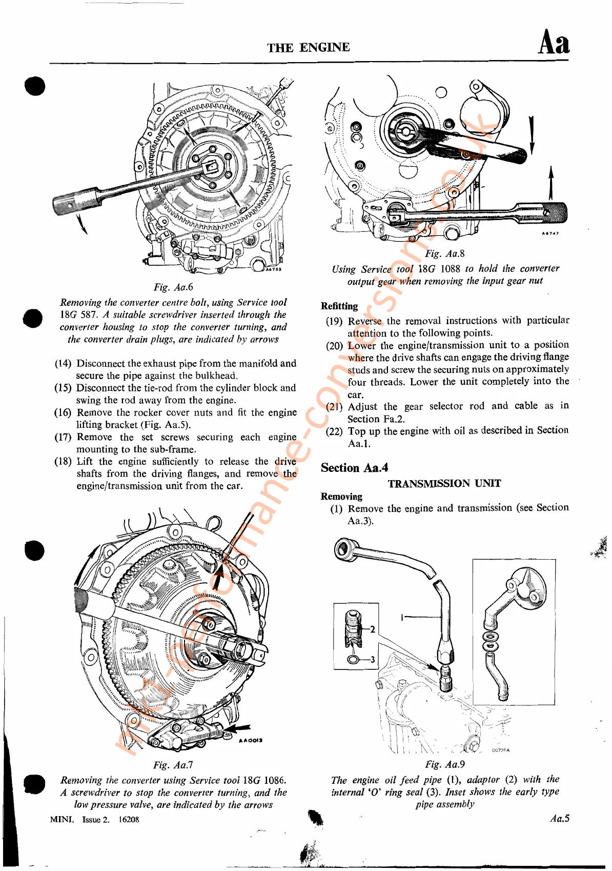
Aa.9
The engine oil
feed
pipe (1), adaptor (2) with the
internal
'0'
ring seal (3). Inset shows the early type
pipe assembly
Fig. Aa.8
Using Service tool
18G 1088 to hold the converter
output gear when removing the input gear nut
Refitting
(19) Reverse the removal instructions with particular
attention
to
the following points.
(20)
Lower the engine/transmission unit to a position
where the drive shafts can engage the driving flange
studs and screw the securing nuts on approximately
four threads. Lower the unit completely into the
car.
(21) Adjust the gear selector rod
and
cable as in
Section Fa.2.
(22)
Top
up the engine with oil as described in Section
Aa.l.
Section Aa.4
TRANSMISSION UNIT
Removing
(1) Remove the engine
and
transmission (see Section
Aa.3).
THE ENGINE
Fig.
Aa.6
Removing the converter centre bolt, using Service tool
180
587.
A suitable screwdriver inserted through the
converter housing to stop the converter turning, and
the converter drain plugs, are indicated by arrows
(14) Disconnect the exhaust pipe from the manifold and
secure the pipe against the bulkhead.
(15) Disconnect the tie-rod from the cylinder block and
swing the rod away from the engine.
(16) Remove the rocker cover nuts and
fit
the engine
lifting bracket (Fig. Aa.5).
(17) Remove the set screws securing each engine
mounting to the sub-frame.
(18) Lift the engine sufficiently to release the drive
shafts from the driving flanges, and remove the
engine/transmission unit from the car.
Fig. Aa.7
Removing the converter using Service
tool18G
1086.
A screwdriver to stop the converter turning, and the
low pressure valve, are indicated
by
the arrows
MINI.
Issue 2. 16208
•
•
•
.'
mk1-performance-conversions.co.uk