Aa
THE
ENGINE
•
•
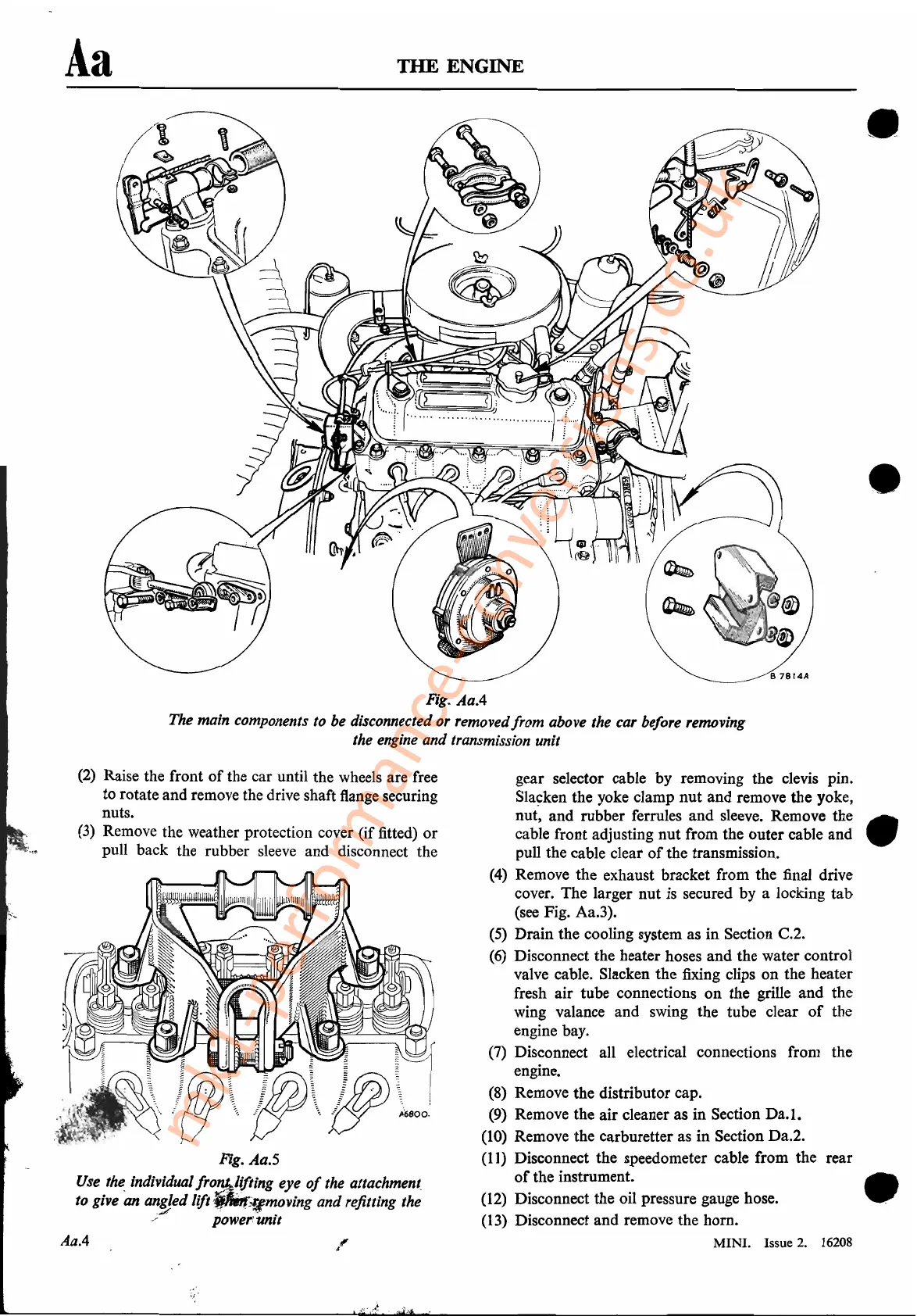
Fig.
Aa.5
Use
t~
individual
fro~Jifting
eye
of
the attachmen(
to give an an!Jed lift
~i"I~oVing
and refitting the
/ power'unlt
(2)
Raise the front
of
the car until the wheels are free
to rotate and remove the drive shaft flange securing
nuts.
(3)
Remove the weather protection cover (if fitted)
or
pull back the rubber
sleeve
and disconnect the
•
•
gear selector cable by removing the clevis pin.
Sla~ken
the yoke clamp nut and remove the yoke,
nut, and rubber ferrules and sleeve. Remove the
cable front adjusting nut from the outer cable and
pull the cable clear
of
the transmission.
(4)
Remove the exhaust bracket from the final drive
cover. The larger nut
is
secured by a locking tab
(see Fig. Aa.3).
(5)
Drain the cooling system as in Section C.2.
(6)
Disconnect the heater hoses and the water control
valve cable. Slacken the fixing clips on the heater
fresh air tube connections on the grille and the
wing valance and swing the tube clear
of
the
engine bay.
(7)
Disconnect all electrical connections from the
engine.
(8)
Remove the distributor cap.
(9)
Remove the air cleaner as in Section
Da.l.
(10)
Remove the carburetter as in Section Da.2.
(11)
Disconnect the speedometer cable from the rear
of
the instrument.
(12)
Disconnect the oil pressure gauge hose.
(13)
Disconnect and remove the horn.
MINI.
Issue 2. 16208
l'
Fig.
AaA
The main components to be disconnected or removedfrom above the car before removing
the engine and transmission unit
AaA
mk1-performance-conversions.co.uk