THE
BODY
R
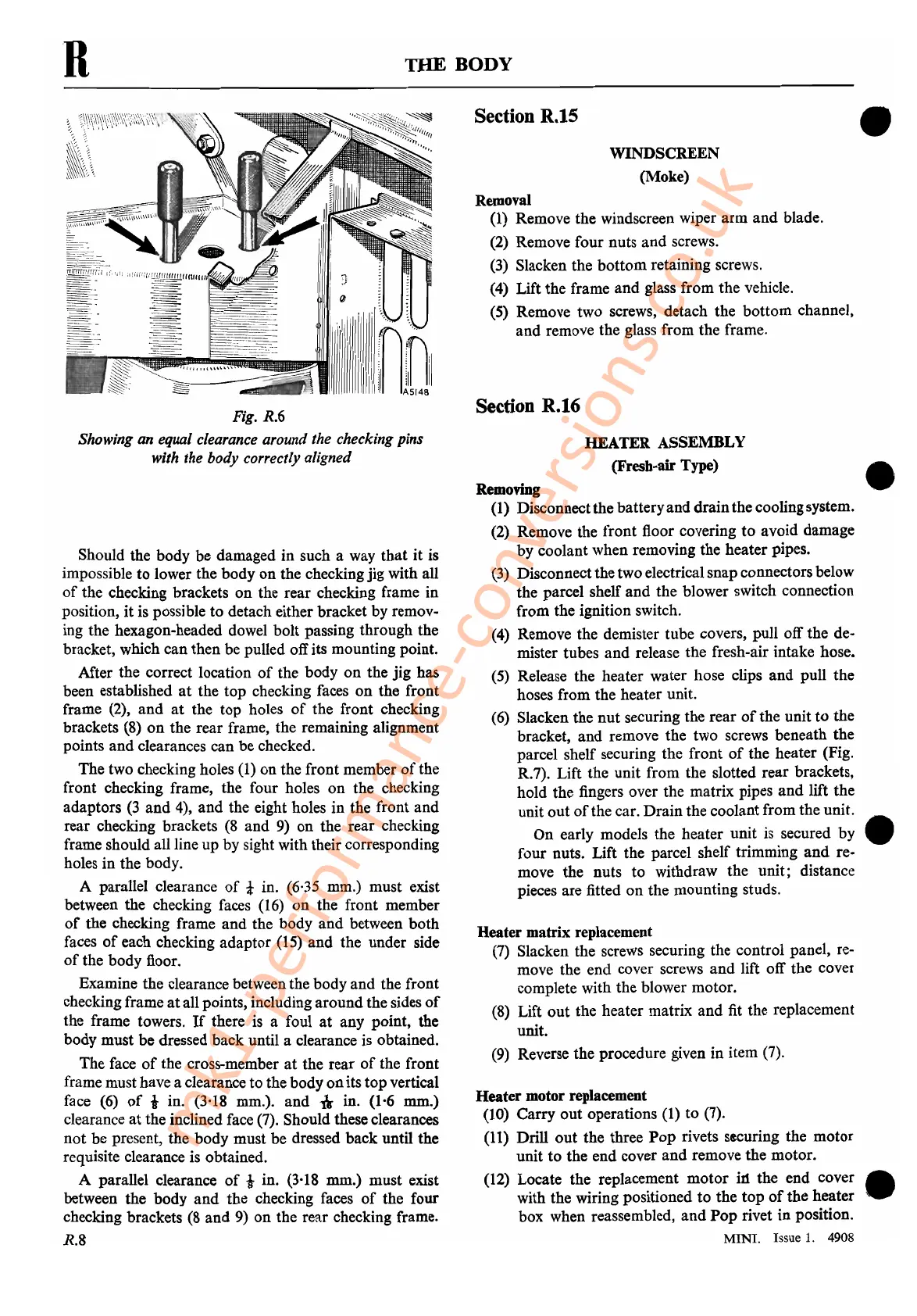
Fig.
R.6
Showing
an
equal clearance around the checking pins
with the body correctly aligned
Should
the
body be damaged
in
such a way
that
it
is
impossible
to
lower
the
body
on
the checking
jig
with all
of
the checking brackets
on
the
rear
checking frame
in
position,
it
is possible
to
detach either bracket by remov-
ing
the
hexagon-headed dowel
bolt
passing
through
the
bracket, which
can
then
be
pulled off its mounting point.
After
the
correct location
of
the
body
on
the
jig
has
been established
at
the
top
checking faces
on
the
front
frame (2),
and
at
the
top
holes
of
the
front
checking
brackets (8)
on
the
rear
frame, the remaining alignment
points
and
clearances
can
be
checked.
The
two checking holes (1)
on
the
front
member
of
the
front checking frame, the
four
holes
on
the
checking
adaptors
(3
and
4),
and
the eight holes
in
the front
and
rear
checking brackets (8
and
9)
on
the
rear
checking
frame should all line
up
by
sight with their corresponding
holes
in
the body.
A parallel clearance
of
! in. (6,35 mm.)
must
exist
between the checking faces
(16)
on
the
front
member
of
the
checking frame
and
the
body
and
between
both
faces
of
each checking
adaptor
(15)
and
the
under
side
of
the
body
floor.
Examine
the
clearance between the
body
and
the
front
checking frame
at
all points, including
around
the sides
of
the
frame towers.
If
there is a foul
at
any
point,
the
body
must
be
dressed
back
until a clearance is obtained.
The
face
of
the cross-member
at
the
rear
of
the
front
frame musthave a clearance
to
the
body
on
its
top
vertical
face
(6)
of
-1
in. (3'18 mm.).
and
,\
in. (1-6 mm.)
clearance
at
the inclined face (7). Should these clearances
not
be present, the
body
must
be
dressed
back
until
the
requisite clearance is obtained.
A parallel clearance
of
-1
in. (3'18 mm.)
must
exist
between
the
body
and
the checking faces
of
the
four
checking brackets
(8
and
9)
on
the
rear
checking frame.
R.S
Section R.15
WINDSCREEN
(Moke)
Removal
(1) Remove
the
windscreen wiper
arm
and
blade.
(2) Remove
four
nuts
and
screws.
(3) Slacken
the
bottom
retaining screws.
(4) Lift
the
frame
and
glass
from
the
vehicle.
(5) Remove two screws,
detach
the
bottom
channel.
and
remove the glass
from
the
frame.
Section R.16
HEATER
ASSEMBLY
(Fresh-air Type)
Removing
(l)
Disconnect
the
battery
and
drain
the
coolingsystem.
(2) Remove the
front
floor covering
to
avoid
damage
by
coolant
when
removing
the
heater
pipes.
(3) Disconnect
the
twoelectrical
snap
connectors below
the
parcel shelf
and
the
blower switch connection
from
the
ignition switch.
(4) Remove the demister
tube
covers,
pull
off
the
de-
mister tubes
and
release
the
fresh-air intake hose.
(5) Release the
heater
water
hose clips
and
pull
the
hoses
from
the
heater
unit.
(6) Slacken the
nut
securing
the
rear
of
the
unit
to
the
bracket,
and
remove
the
two
screws beneath
the
parcel shelf securing
the
front
of
the
heater
(Fig.
R.7). Lift
the
unit
from
the slotted
rear
brackets,
hold
the
fingers over the matrix pipes
and
lift
the
unit
out
of
the car.
Drain
the
coolant
from
the
unit
.
On
early models the
heater
unit
is secured
by
four
nuts. Lift the parcel shelf trimming
and
re-
move
the
nuts
to
withdraw
the
unit;
distance
pieces are fitted
on
the
mounting
studs.
Heater
matrix
replacement
(7) Slacken
the
screws securing the
control
panel, re-
move the
end
cover screws
and
lift off
the
cover
complete with the blower
motor.
(8) Lift
out
the
heater
matrix
and
fit the replacement
unit.
(9) Reverse the procedure given
in
item (7).
Heater
motor replacement
(10)
Carry
out
operations (1)
to
(7).
(11) Drill
out
the
three
Pop
rivets securing
the
motor
unit
to
the
end
cover
and
remove
the
motor.
(12) Locate
the
replacement
motor
ill the
end
cover
with
the
wiring positioned
to
the
top
of
the
heater
box when reassembled,
and
Pop
rivet
in
position.
MINI. Issue
1.
4908
•
•
•
•
mk1-performance-conversions.co.uk