•
•
THE
BODY
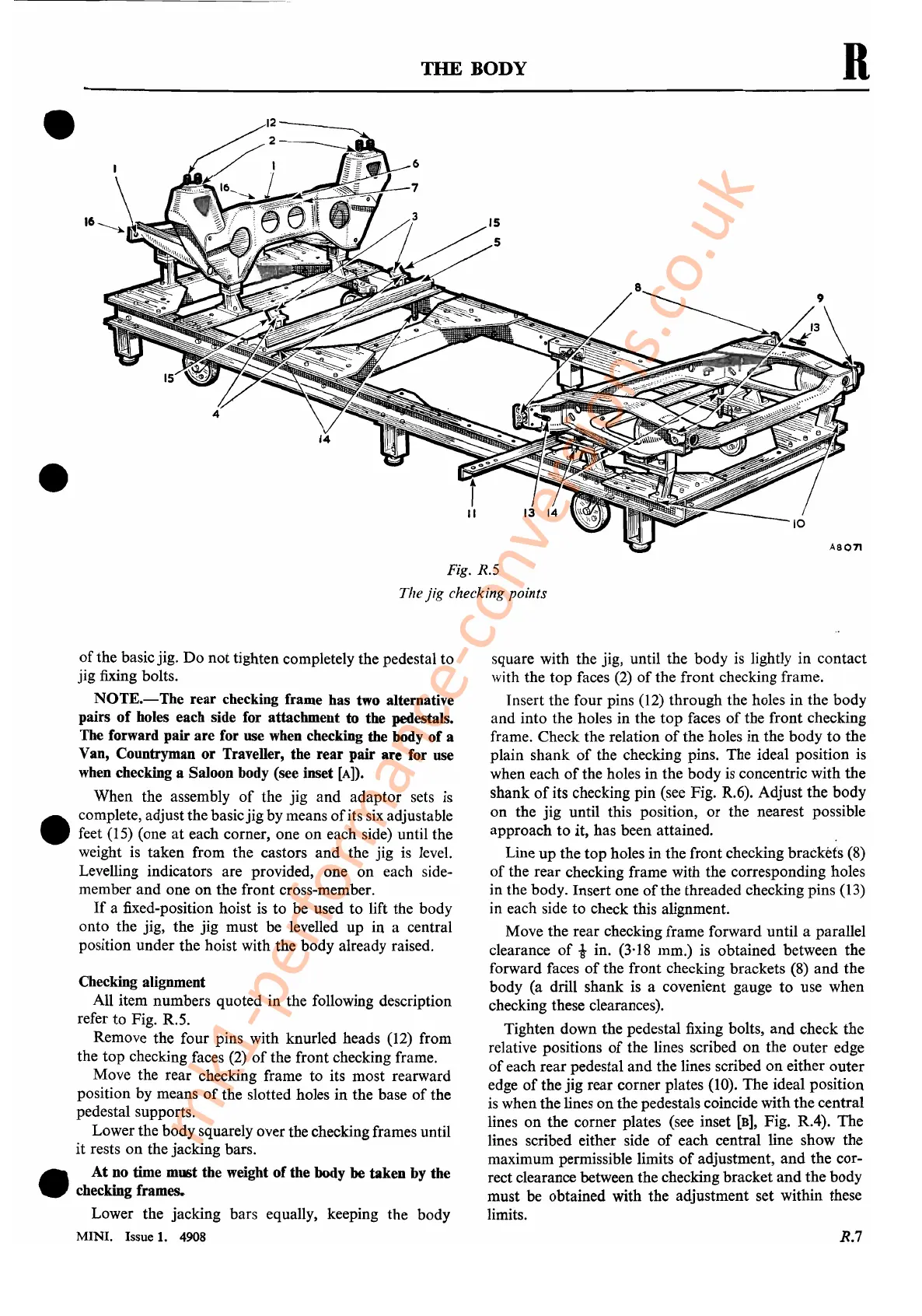
Fig. R.5
The
jig
checking points
R
of
the basicjig.
Do
not tighten completely the pedestal to
jig fixing bolts.
NOTE.-
The rear checking frame has two alternative
pairs
of
holes each side for attachment to the pedestals.
The forward pair are for use
when
checking the body
of
a
Van, Countryman or Traveller, the rear pair are for use
when
checking a Saloon body (see inset
[A]).
When the assembly
of
the jig and adaptor sets is
•
complete, adjust the basicjig by means
of
its
six
adjustable
feet (15) (one
at
each corner, one on each side) until the
weight is taken from the castors
and
the jig is level.
Levelling indicators are provided, one
on
each side-
member
and
one
on
the front cross-member.
If
a fixed-position hoist is to be used to lift the body
onto the jig, the jig must be levelled
up
in a central
position under the hoist with the body already raised.
Checking alignment
All item numbers quoted in the following description
refer to Fig. R.5.
Remove the four pins with knurled heads (12) from
the top checking faces (2)
of
the front checking frame.
Move the rear checking frame to its most rearward
position by means
of
the slotted holes in the base
of
the
pedestal supports.
Lower the body squarely over the checking frames until
it
rests
on
the jacking bars.
•
At no time must the weight of the body
be taken by the
checking frames.
Lower the jacking bars equally, keeping the body
MINI. Issue 1. 4908
square with the jig, until the body
is
lightly in contact
with the
top
faces
(2)
of
the front checking frame.
Insert the four pins (12) through the holes in the body
and
into the holes in the top faces
of
the front checking
frame. Check the relation
of
the holes in the body
to
the
plain shank
of
the checking pins. The ideal position
is
when each
of
the holes in the body
is
concentric with the
shank
of
its checking pin (see Fig. R.6). Adjust the body
on
the jig until this position,
or
the nearest possible
approach to it, has been attained.
Line
up
the
top
holes in the front checking brackets (8)
of
the rear checking frame with the corresponding holes
in the body. Insert one
of
the threaded checking pins (13)
in each side to check this alignment.
Move the rear checking frame forward until a parallel
clearance
of
i in. (3'18 mm.) is obtained between the
forward faces
of
the front checking brackets
(8)
and the
body (a drill shank is a covenient gauge
to
use when
checking these clearances).
Tighten down the pedestal fixing bolts,
and
check the
relative positions
of
the lines scribed
on
the outer edge
of
each rear pedestal
and
the lines scribed
on
either outer
edge
of
the jig rear corner plates (10). The ideal position
is
when the lines on the pedestals coincide with the central
lines
on
the corner plates (see inset
[B],
Fig. RA).
The
lines scribed either side
of
each central line show the
maximum permissible limits
of
adjustment,
and
the cor-
rect clearance between the checking bracket
and
the body
must be obtained with the adjustment set within these
limits.
R.7
mk1-performance-conversions.co.uk