8
THE
BODY
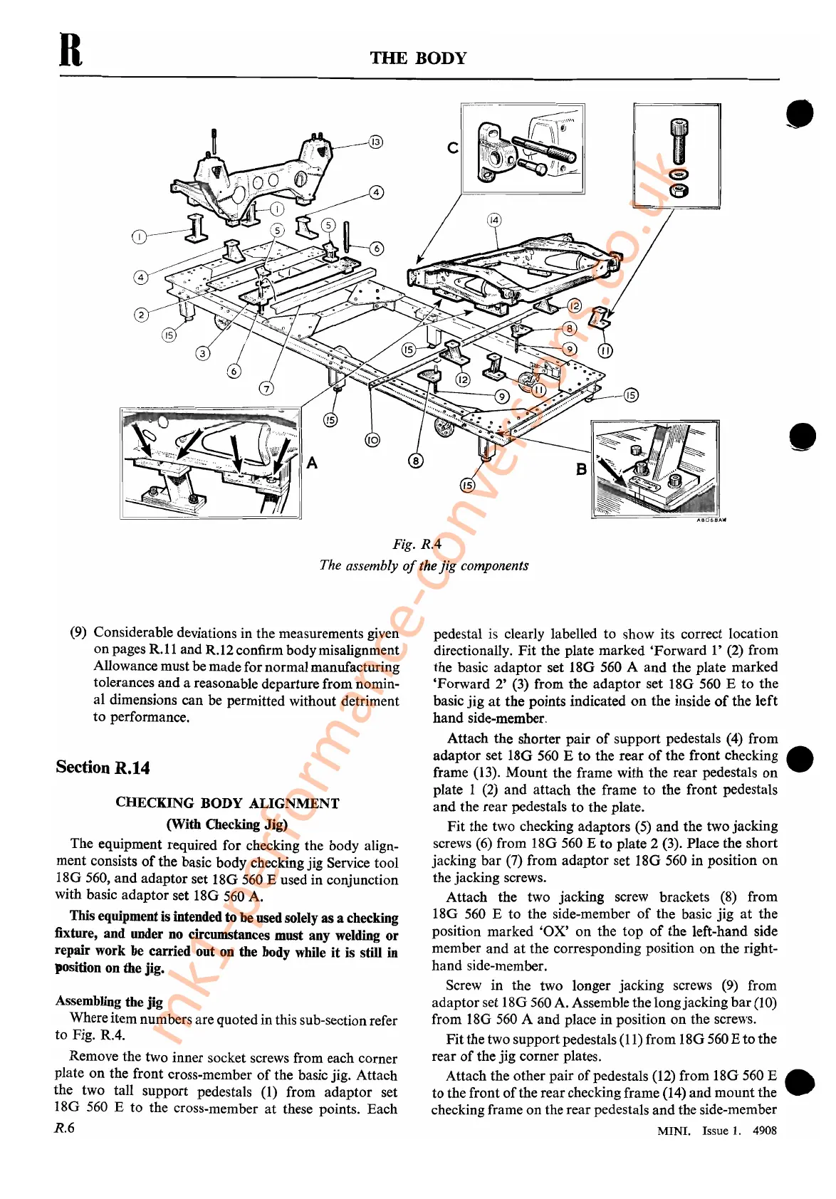
Fig.
RA
The assembly
of
the
jig
components
•
•
(9)
Considerable deviations in the measurements given
on pages
R.II
and R.12 confirm bodymisalignment
Allowance must be madefor normal manufacturing
tolerances
and
a reasonable departure from nomin-
al dimensions can be permitted without detriment
to
performance.
Section R.14
CHECKING BODY ALIGNMENT
(With Checking Jig)
The equipment required for checking the body align-
ment consists
of
the basic body checking jig Service tool
I8G
560,
and
adaptor set
I8G
560
E used in conjunction
with basic adaptor set 18G 560 A.
This equipment is intended to be used solely as a checking
fixture, and under no circumstances must any welding
or
repair work be carried out on the body while
it
is still in
position on the jig.
Assembling the jig
Where item numbers are quoted in this sub-sectionrefer
to
Fig. R.4.
Remove the two inner socket screws from each corner
plate
on
the front cross-member
of
the basic jig. Attach
the two tall support pedestals
(1)
from adaptor set
18G 560 E to the cross-member
at
these points. Each
R.6
pedestal
is
clearly labelled to show its correct location
directionally.
Fit
the plate marked 'Forward
I'
(2) from
the basic adaptor set
180
560 A
and
the plate marked
'Forward
2'
(3) from the adaptor set
I8G
560 E to the
basic
jig
at
the
points indicated
on
the inside
of
the
left
hand side-member.
Attach the shorter pair
of
support pedestals (4) from
adaptor set
180
560
E
to
the rear
of
the front checking •
frame (13).
Mount
the frame with the rear pedestals
on
plate I
(2)
and attach the frame to the front pedestals
and
the rear pedestals
to
the plate.
Fit
the two checking adaptors (5)
and
the two jacking
screws
(6)
from 18G 560 E to plate 2 (3). Place the short
jacking
bar
(7) from adaptor set 18G 560 in position
on
the jacking screws.
Attach the two jacking screw brackets
(8)
from
18G
560
E
to
the side-member
of
the basic jig
at
the
position marked
'OX'
on
the
top
of
the left-hand side
member
and
at
the corresponding position
on
the right-
hand side-member.
Screw in the two longer jacking screws
(9)
from
adaptor set
I8G
560
A. Assemble the longjacking
bar
(10)
from 18G
560
A
and
place in position
on
the screws.
Fit
the two supportpedestals (11) from 18G560 E
to
the
rear
of
the jig corner plates.
Attach the other pair
of
pedestals (12) from 18G 560 E •
to
the front
of
the rear checking frame (14)
and
mount the
checking frame on the rear pedestals
and
the side-member
MINI.
Issue
1.
4908
mk1-performance-conversions.co.uk