THE
ENGINE
•
•
•
•
Refitting
(7) Reverse the removal instructions.
NOTES.-Pull
the gear lever
up
into the interior
of the car before the engine is lowered into position.
Keep
the sliding joints pushed
well
onto the drive
shaft splines
while
the flexible couplings are
moved
into position.
COOPER
Removing
(1)
Carry out the instructions
(1)
to
(10)
and
(15)
in
Section A.I2.
(2)
Remove the fresh-air motor (when fitted).
(3) Disconnect the oil gauge pipe.
(4) Take offthe distributor cap.
(5) Remove the carburetters and air cleaners (Sections
A.I and A.2).
(6) Remove the exhaust pipe assembly (Section A.3).
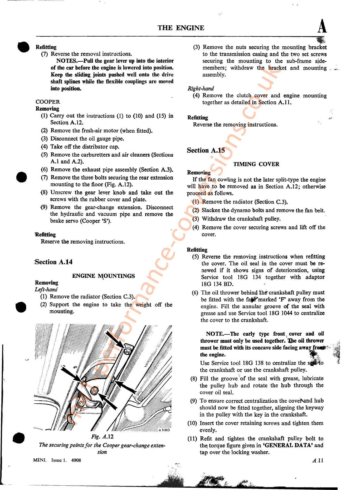
(7) Remove the three bolts securing the rear extension
mounting to the floor (Fig. A.I2).
(8) Unscrew the gear lever knob and take out the
screws with the rubber cover and plate.
(9) Remove the gear-change extension. Disconnect
the hydraulic and vacuum pipe and remove the
brake servo (Cooper'S').
Refitting
Reserve the removing instructions.
:Section A.14
ENGINE
~OUNTINGS
Removing
Left-hand
(l)
Remove the radiator (Section C.3).
(2)
Support the engine to take the weight off the
mounting.
11'
Fig.
A.l2
The securing points
for
the Cooper gear-change exten-
sion
MINI. Issue
1.
4908
A
_.
(3)
Remove the nuts securing the mounting bracket
to the transmission casing and the two set screws
securing the mounting
to
the sub-frame sjde-
members; withdraw the bracket and mounting
_,"'-','
assembly.
Right-hand
(4) Remove the clutch cover
and
engine mounting
together as detailed in Section
A.II.
Refitting
Reverse the removing instructions.
Section A.1S
TIMING COVER
Removing
If
the fan cowling is not the later split-type the engine
will have to be removed as in Section A.12; otherwise
proceed as follows.
(1) Remove the radiator (Section C.3).
(2)
Slacken the dynamo bolts and remove the fan belt.
(3)
Withdraw the crankshaft pulley.
(4)
Remove the cover securing screws and lift off the
cover.
Refitting
(5)
Reverse the removing instructions when refitting
the cover. The oil seal in the cover must be re-
newed
if
it shows signs
of
deterioration, .usins
Service tool 18G
134
together with adaptor
18G
134
BD.
(6)
The oil thrower
behin41ht
crankshaft pulley must
be fitted with the
fa,~marked
'F'
away from the
engine. Fill the annular groove
of
the seal with
grease and use Service
tool18G
1044
to centralize
the cover to the crankshaft. .
NOTE.-Tbe
early type front
~
cover and oil
thrower must only
be
used together.
~e
oil thrower
,:~
must be fitted with its concave side facing
away:
fr_1'::';~;
the
engine.l!k..
":,:
Use Service
tool18G
138
to centralize the
s_to
;~
the crankshaft
or
use the crankshaft pulley.
(8)
Fill the groove
'~of
the seal with grease, lubricate
the pulley hub and rotate the
hub
through the
cover oil seal.
(9)
To ensure correct centralization the covel'.a,nd hub
should now be fitted together, aligning the keyway
in the pulley with the key in the crankshaft.
Cl
0)
Insert the cover retaining screws and tighten them
evenly.
(11) Refit and tighten the crankshaft' pulley bolt to
the,
torque figure given in 'GENERAL DATA' and
tap over the locking washer.
A.11
mk1-performance-conversions.co.uk