THE ENGINE
Aa
A6746B
Aa.9
3
____
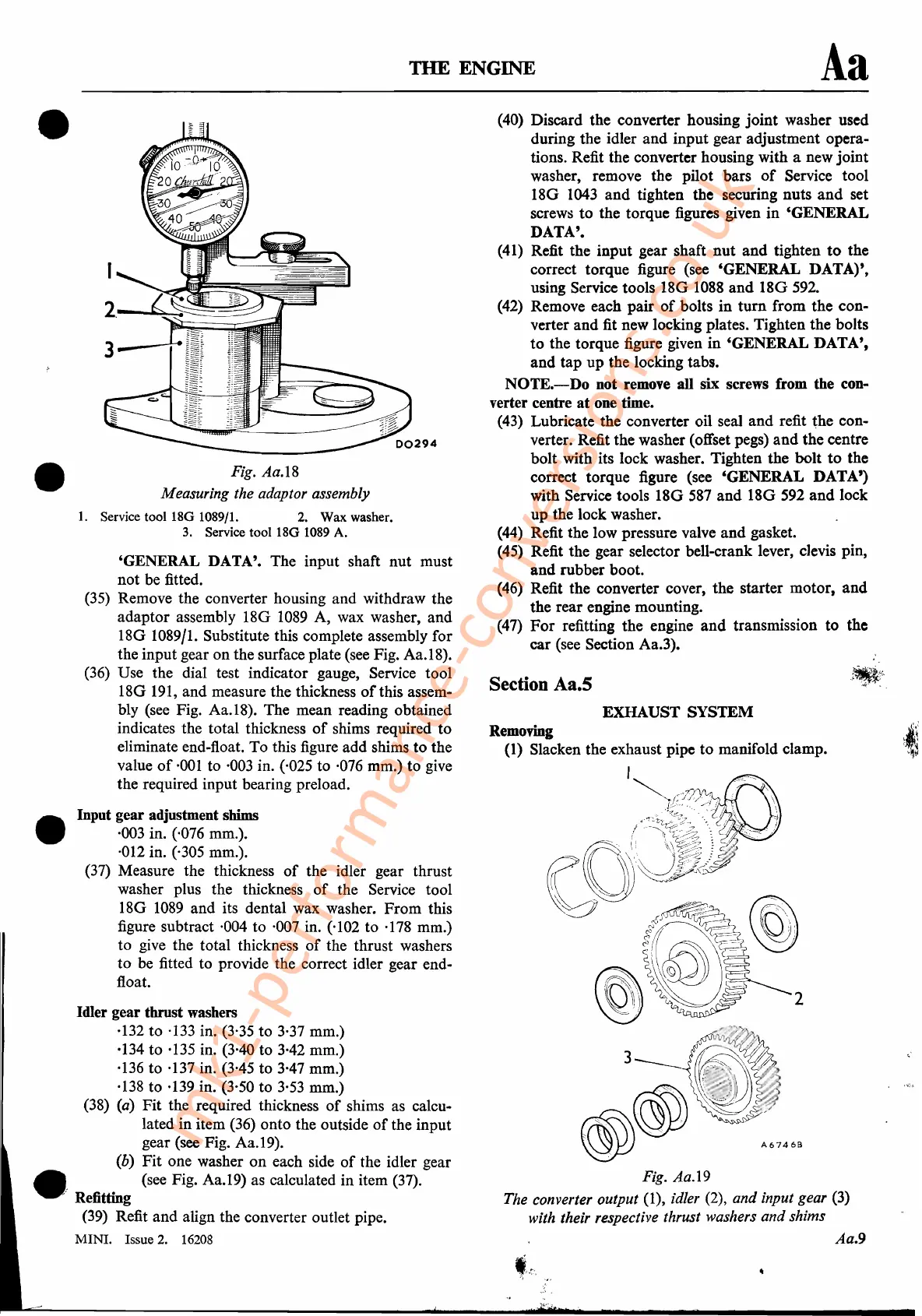
Fig. Aa.19
The converter output
(1), idler (2), and input gear (3)
with their respective thrust washers and shims
(40) Discard the converter housing
joint
washer used
during the idler and input gear adjustment opera-
tions. Refit the converter housing with a new joint
washer, remove the pilot bars
of
Service tool
18G
1043
and
tighten the securing nuts
and
set
screws
to
the torque figures given
in
'GENERAL
DATA'.
(41) Refit the input gear shaft
nut
and
tighten
to
the
correct torque figure (see 'GENERAL DATA)',
using Service tools
180
1088
and
180592.
(42) Remove each pair
of
bolts
in
turn
from the con-
verter and fit new locking plates. Tighten the bolts
to
the torque figure given
in
'GENERAL DATA',
and
tap
up
the locking tabs.
NOTE.-Do
not remove all six screws from the con-
verter centre
at
one time.
(43) Lubricate the converter oil seal
and
refit the con-
verter. Refit the washer (offset pegs)
and
the centre
bolt with its lock washer. Tighten the bolt
to
the
correct torque figure (see 'GENERAL DATA')
with Service tools
180
587
and
180
592
and
lock
up
the lock washer.
(44) Refit the low pressure valve
and
gasket.
(45) Refit the gear selector bell-crank lever, clevis pin,
and
rubber boot.
(46) Refit the converter cover, the starter motor,
and
the rear engine mounting.
(47)
For
refitting the engine
and
transmission to the
car (see Section Aa.3).
EXHAUST SYSTEM
Removing
(1) Slacken the exhaust pipe
to
manifold clamp.
I
;P._.~
~~/;:7J{jll!.
,...
..
\
("~~~~~u
I/;,'k;
Section Aa.5
Fig. Aa.18
Measuring the adaptor assembly
1.
Service tool 18G 1089/1. 2. Wax washer.
3. Service
tool18G
1089
A.
'GENERAL DATA'. The input shaft
nut
must
not be fitted.
(35)
Remove the converter housing and withdraw the
adaptor assembly 18G
1089
A, wax washer, and
180
1089/1. Substitute this complete assembly for
the input gear on the surface plate (see Fig. Aa.18).
(36) Use the dial test indicator gauge, Service tool
18G
191,
and measure the thickness
of
this assem-
bly (see Fig. Aa.18). The mean reading obtained
indicates the total thickness
of
shims required
to
eliminate end-float. To this figure add shims
to
the
value
of
·001
to
·003
in. ('025 to ·076 mm.) to give
the required input bearing preload.
Input gear adjustment shims
·003 in. (,076 mm.).
·012 in. (,305 mm.).
(37) Measure the thickness
of
the idler gear thrust
washer plus the thickness
of
the Service tool
18G
1089
and its dental wax washer.
From
this
figure subtract ·004 to ·007 in. ('102 to ·178 mm.)
to give the total thickness
of
the thrust washers
to
be fitted to provide the correct idler gear end-
float.
•
Idler gear thrust washers
·132
to
·133 in. (3'35 to 3·37 mm.)
·134
to
·135 in. (3'40 to 3·42 mm.)
·136 to ·137 in. (3'45 to 3'47 mm.)
·138
to ·139 in. (3,50 to 3'53 mm.)
(38)
(a)
Fit the required thickness
of
shims as calcu-
lated in item (36) onto the outside
of
the input
gear (see Fig. Aa.19).
(b)
Fit
one washer
on
each side
of
the idler gear
•
' (see Fig. Aa.19) as calculated in item (37).
, Refitting
(39) Refit
and
align the converter outlet pipe.
MINI.
Issue 2.
16208
•
•
mk1-performance-conversions.co.uk