THE
ENGINE
Aa
(2) Release the pipe from the bracket
on
the final
drive casing (Fig. Aa.3)
and
from the two locations
on
the rear sub-frame.
Refitting
(3) Refit the exhaust system to the car with the inter-
mediate
and
rear support clips loose
to
allow
articulation
at
the manifold spherical flange.
(4) Align
the
pipe flange with the manifold, refit
and
tighten the manifold clamp.
(5) Ensure correct alignment
of
the system
and
tighten
the remaining fixing points.
Section Aa.6
DISTRIBUTOR
DRIVING
SPINDLE
Removing
(1) Remove the distributor
and
driving spindle as
detailed
in
Section A.IO.
Refitting
(2) Refitting is described
in
Section A.IO with the
following exceptions.
(3)
To
rotate the crankshaft, insert a screwdriver
through the aperture (adjacent the oil dipstick)
on
the converter housing,
and
turn
the converter
starter ring gear
to
the position described
in
Section A.lO.
(4) Check
that
the 1/4 timing
mark
on
the converter
is
in
line with the pointer
on
the converter housing
(Fig. Ba.1).
Section Aa.7
VALVE
TIMING
(1) Follow the instructions given in Section
A.I?
with
the following exceptions.
(2)
Rotate
the crankshaft as described
in
Se6tion Aa.6
until the 5°
B.T.D.e.
timing
mark
on
the con-
verter is opposite the pointer
on
the converter
cover.
Section Aa.8
OIL
PUMP
Removing
(1) Remove the engine and transmission as detailed
in
Section Aa.3.
(2)
Remove the converter
and
converter housing as
detailed
in
Section AaA, items (3)
to
(12).
(3) Remove the
pump
securing screws
and
withdraw
h.
."
the. pump.
Dismantling and reassembling
(4) Follow the instructions given in Section A.22 for
the Hobourn-Eaton pump.
Refitting
(5) Reverse the removal instructions fitting new
joint
washers as required.
Aa.IO
•
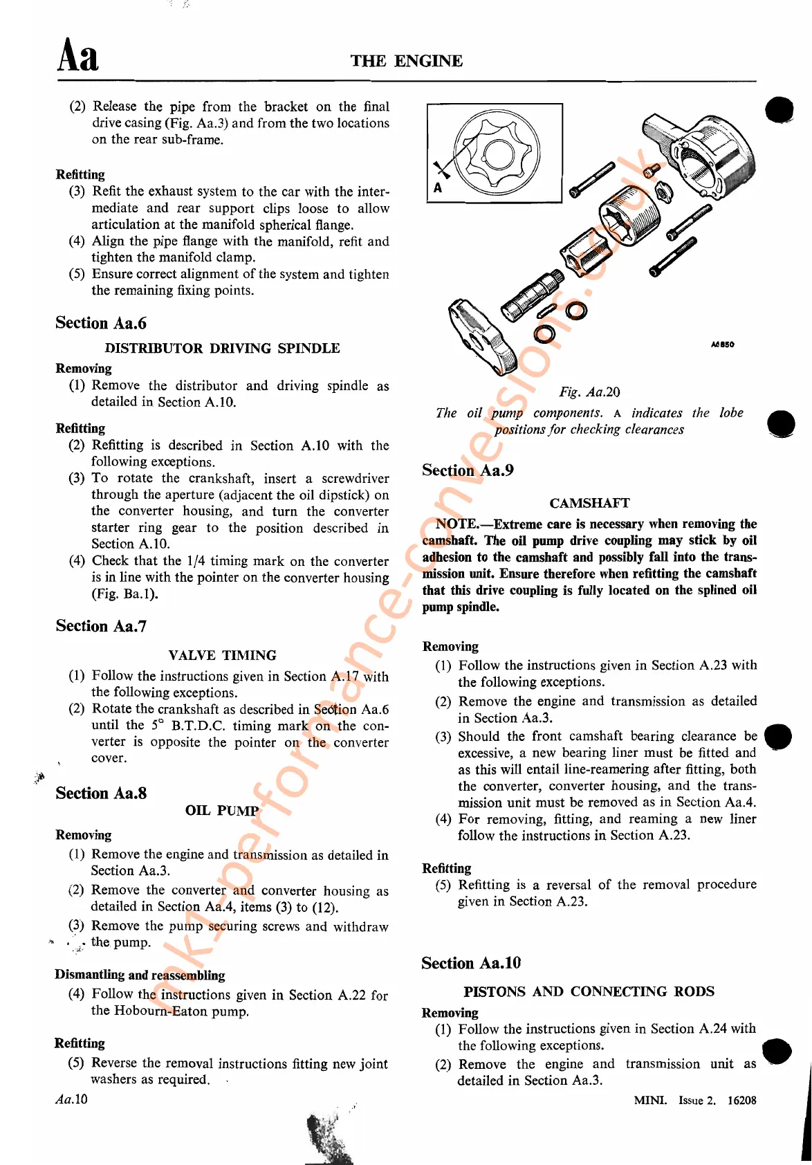
Fig. Aa.20
The oil pump components.
A indicates the lobe •
positions
for
checking clearances _ .
Section Aa.9
CAMSHAFT
NOTE.-Extreme
care is necessary when removing the
camshaft. The oil pump drive coupling may stick by oil
adhesion to the camshaft and possibly fall into the trans-
mission unit. Ensure therefore when refitting the camshaft
that
this drive coupling is fully located on the splined oil
pump spindle.
Removing
(1) Follow the instructions given
in
Section A.23 with
the following exceptions.
(2) Remove the engine
and
transmission as detailed
in Section Aa.3.
(3) Should the front camshaft bearing clearance be •
excessive, a new bearing liner must be fitted
and
as this will entailline-reamering after fitting,
both
the converter, converter housing,
and
the
trans-
mission
unit
must
be removed as
in
Section AaA.
(4)
For
removing, fitting,
and
reaming a new liner
follow the instructions
in
Section A.23.
Refitting
(5) Refitting is a reversal
of
the removal procedure
given in Section A.23.
Section Aa.tO
PISTONS
AND
CONNECTING
RODS
Removing
(1) Follow the instructions given
in
Section A.24 with
the following exceptions. •
(2) Remove the engine
and
transmission
unit
as
.-
detailed
in
Section Aa.3.
MINI. Issue
2.
16208
mk1-performance-conversions.co.uk