THE
ELECTRICAL SYSTEM
N
Section N.8
•
Wiring
Check for continuity between each unit. Check for
leak
to
earth. Check for short circuits
to
earth
on
wiring
to
each transmitter. Check terminal wiring for security,
earth connections,
and
wiring continuity. Check
that
the
voltage stabilizer
and
relating transmitters are earthed.
NOTE.-H
the
voltage stabilizer is removed
it
is
.essential
to
ensure
that,
when replacing,
Band
E
are
uppermost and
not
exceeding 20 degrees from
the
vertical.
WINDSCREEN
WIPER
MOTOR
(Moke)
The wiper
motor
fitted
to
early models
of
this vehicle
operated a single wiping blade
on
the driver's side only.
Later vehicles are equipped with a
motor
which
operates twin wiper blades,
and
this
motor
will be
• referred
to
below as the (later type).
Removing (early type)
(1) Slacken the hexagon screw
and
pull the-blade
and
arm
from the drive spindle.
(2) Remove the nuts, locknuts, washers,
and
seals
securing the motor
to
the scuttle.
(3)
Disconnect the leads from inside the vehicle
and
withdraw the motor.
NOTE.-A
rubber flange with steel inserts is
fitted. between the wiper
motor
and
the scuttle
to
prevent
the
insulating flange being over-compressed.
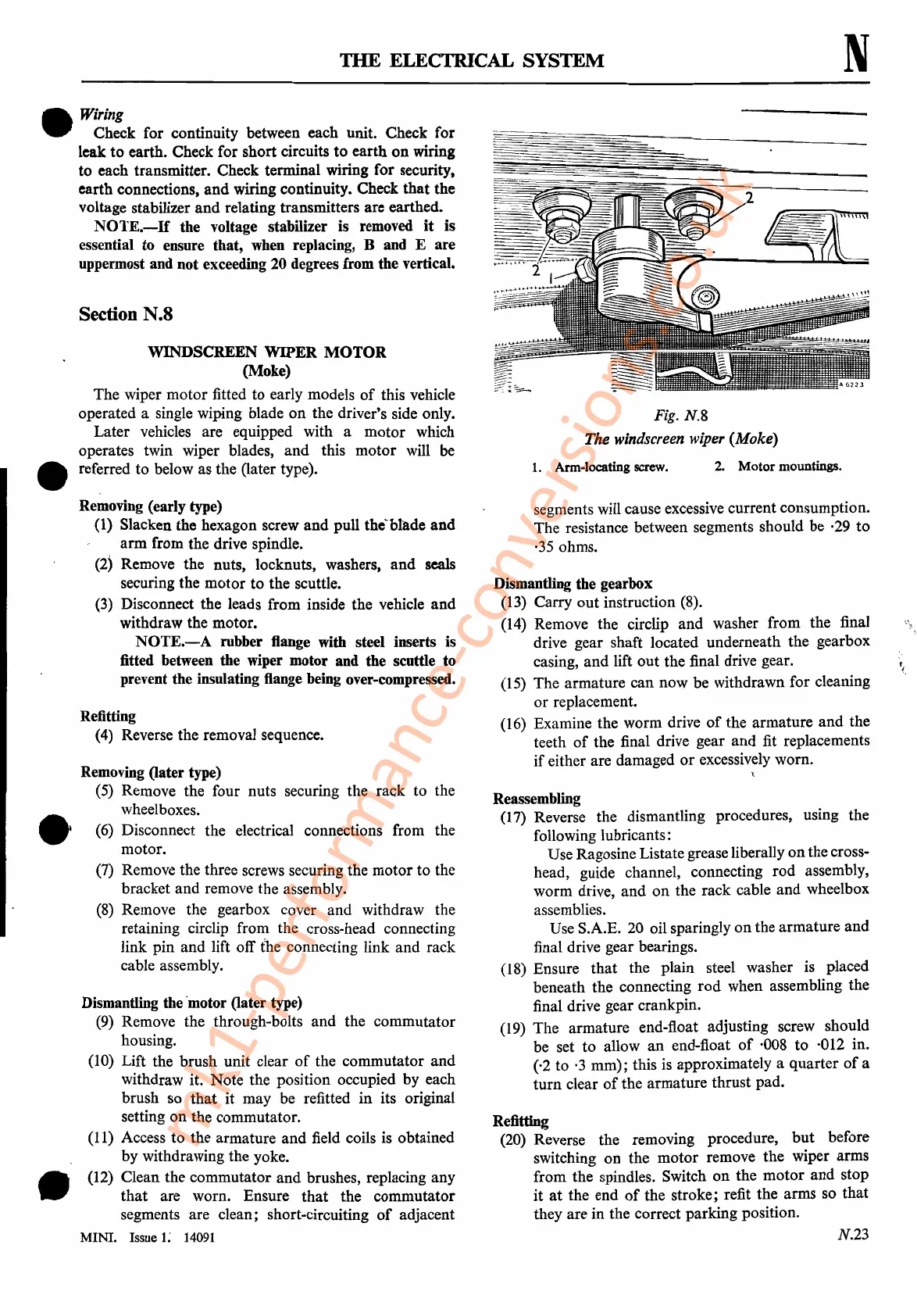
2.
Motor mountings.
1.
Arm-locating screw.
Refitting
(20) Reverse the removing procedure,
but
before
switching
on
the
motor
remove the wiper arms
from the spindles. Switch
on
the
motor
and
stop
it
at
the end
of
the stroke; refit the arms so that
they are in the correct parking position.
Reassembling
(17) Reverse the dismantling procedures, using the
following lubricants:
Use Ragosine Listate grease liberally
on
thecross-
head, guide channel, connecting
rod
assembly,
worm drive,
and
on
the rack cable
and
wheelbox
assemblies.
U
se
S.A.E. 20 oil sparingly
on
the
armature
and
final drive gear bearings.
(18) Ensure
that
the plain steel washer is placed
beneath
the
connecting
rod
when assembling the
final drive gear crankpin.
(19) The armature end-float adjusting screw should
be set
to
allow
an
end-float
of
·008
to
·012 in.
(,2 to
·3
mm); this is approximately a quarter
of
a
turn
clear
of
the armature thrust pad.
Dismantling the gearbox
(13) Carry
out
instruction (8).
(14) Remove the circlip
and
washer from the final
drive gear shaft located underneath the gearbox
casing,
and
lift
out
the final drive gear.
(15) The armature can now be withdrawn for cleaning
or
replacement.
(16) Examine the worm drive
of
the armature
and
the
teeth
of
the final drive gear and fit replacements
if
either are damaged
or
excessively worn.
\
segments will cause excessive current consumption.
The resistance between segments should be ·29
to
·35
ohms.
N.23
Fig. N.8
The
windscreen
wiper
(Moke)
Removing (later type)
(5) Remove the four nuts securing the rack to the
wheelboxes.
(6) Disconnect the electrical connections from the
motor.
(7) Remove the three screws securing the
motor
to the
bracket and remove the assembly.
(8)
Remove the gearbox cover and withdraw the
retaining circlip from the cross-head connecting
link pin
and
lift off tbe connecting link and rack
cable assembly.
Dismantling
the
·motor (later type)
(9)
Remove the through-bolts
and
the commutator
housing.
(l0) Lift the brush unit clear
of
the commutator
and
withdraw it. Note the position occupied by each
brush so
that
it
may be refitted
in
its original
setting
on
the commutator.
(11) Access
to
the armature
and
field coils is obtained
by withdrawing the yoke.
(12) Clean the commutator and brushes, replacing any
that
are worn. Ensure
that
the commutator
segments are clean; short-circuiting
of
adjacent
MINI. Issue
1:
14091
Refitting
(4) Reverse the removal sequence.
•
•
mk1-performance-conversions.co.uk



 To Next Page