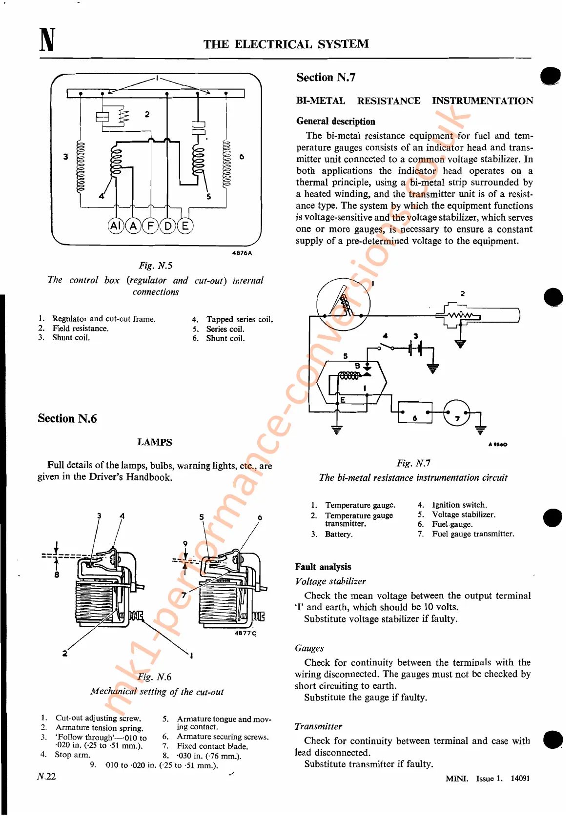
Fig. N.S
The control
box
(regulator and cut-out) infernal
connections
N
1.
Regulator
and
cut-out frame.
2. Field resistance.
3.
Shunt coil.
Section N.6
LAMPS
THE
ELECTRICAL SYSTEM
Section N.7
BI-METAL RESISTANCE INSTRUMENTATION
General description
The bi-metal resistance equipment for fuel
and
tem-
perature gauges consists
of
an
indicator head
and
trans-
mitter unit connected
to
a common voltage stabilizer.
In
both
applications the indicator head operates on a
thermal principle, using a bi-metal strip surrounded by
a heated winding,
and
the transmitter unit is
of
a resist-
ance type. The system by which the equipment functions
is voltage-sensitive and the voltage stabilizer, which serves
one
or
more gauges, is necessary
to
ensure a constant
supply
of
a pre-determined voltage
to
the equipment.
4876A
2
4.
Tapped
series coil.
5. Series coil.
6.
Shunt
coil.
10"60
•
•
Full details
of
the lamps, bulbs, warning lights, etc., are
given in the Driver's Handbook.
Fig. N.6
Mechanical setting
of
the cut-out
3
4
4877'C.
Fig. N.?
The hi-metal resistance instrumentation circuit
1.
Temperature gauge.
4.
Ignition switch.
2.
Temperature gallge
5.
Voltage stabilizer.
transmitter.
6. Fuel gauge.
3.
Battery.
7.
Fuel
gauge transmitter.
Fault analysis
Voltage stabilizer
Check the mean voltage between the
output
terminal
'I'
and earth, which should be
10
volts.
Substitute voltage stabilizer
if
faulty.
Gauges
Check for continuity between the terminals with the
wiring disconnected. The gauges must
not
be checked by
short Circuiting
to
earth.
Substitute the gauge
if
faulty.
•
1. Cut-out adjusting screw. 5. Armature tongue
and
mov-
2.
Armature
tension spring. ing contact.
3.
'Follow
through'-·OlO
to
6.
Armature
securing screws.
·020 in. (·25 to
·51
mm.). 7. Fixed contact blade.
4.
Stop
arm.
8.
·030 in. (,76 mm.).
9.
·010 to ·020 in. (,25 to '51 mm.).
N.22
Transmitter
Check for continuity between terminal
and
case with •
lead disconnected.
Substitute transmitter
if
faulty.
MINI.
Issue 1.
14091
mk1-performance-conversions.co.uk



 To Next Page