THE ELECTRICAL'
SYSTEM
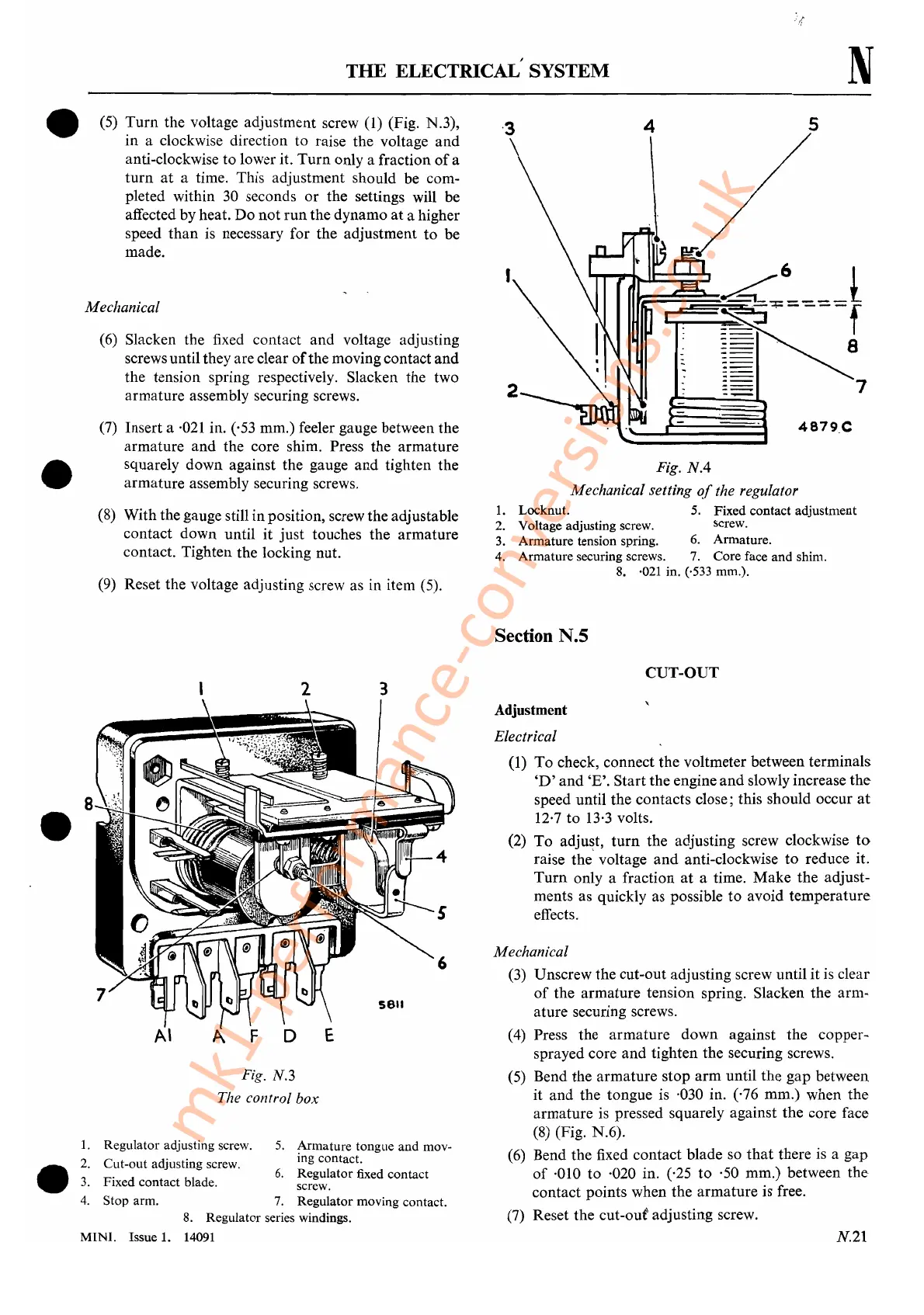
Fig.
NA
Mechanical setting
of
the regulator
1. Locknut. 5. Fixed contact adjustment
2. Voltage adjusting screw. screw.
3.
Armature
tension spring.
6.
Armature.
4.
Armature
securing screws. 7.
Core
face
and
shim.
8. ·021 in.
(,533 mm.).
•
•
(5)
Turn
the voltage adjustment screw (1) (Fig. N.3),
in
a clockwise direction
to
raise the voltage
and
anti-clockwise
to
lower it.
Turn
only a fraction
of
a
turn
at
a time. This adjustment should be com-
pleted within 30 seconds
or
the settings will be
affected
by
heat.
Do
not
run
the dynamo
at
a higher
speed
than
is necessary for the adjustment
to
be
made.
Mechanical
(6) Slacken the fixed contact
and
voltage adjusting
screws until they are clear
of
the moving contact
and
the tension spring respectively. Slacken the two
armature
assembly securing screws.
(7) Insert a
·021
in. (,53 mm.) feeler gauge between the
armature
and
the core shim. Press the
armature
squarely down against the gauge
and
tighten
the
armature
assembly securing screws.
(8) With the gauge still in position, screw the adjustable
contact down until it
just
touches the
armature
contact. Tighten the locking nut.
(9) Reset the voltage adjusting screw as in item (5).
4
N
5
7
4879.C
Section N.5
2
3
CUT-OUT
To
check, connect
the
voltmeter between terminals
'D'
and
'E'.
Start
the
engine
and
slowly increase
the
speed until
the
contacts close; this should occur
at
12·7
to
13·3 volts.
To
adjust,
turn
the
adjusting screw clockwise
to
raise the' voltage
and
anti-clockwise
to
reduce it.
Turn
only a fraction
at
a time.
Make
the
adjust-
ments as quickly as possible
to
avoid
temperature
effects.
(1)
(2)
Mechanical
(3) Unscrew the cut-out adjusting screw until
it
is clear
of
the
armature
tension spring. Slacken the arm-
ature securing screws.
(4) Press the
armature
down
against
the
copper-
sprayed core
and
tighten the securing screws.
(5) Bend
the
armature
stop
arm
until the
gap
between
it
and
the tongue is ·030 in. ('76 mm.) when
the
armature
is pressed squarely against
the
core face
(8) (Fig. N.6).
(6) Bend the fixed contact blade so
that
there is a gap
of
·010
to
·020 in. (,25
to
·50 mm.) between
the
contact points when the
armature
is free.
(7) Reset the cut-ouiVadjusting screw.
Adjustment
Electrical
Fig. N.3
The control
box
5.
Armature tongue
and
mov-
ing contact.
6.
Regulator fixed contact
screw.
7.
Regulator moving contact.
8.
Regulator series windings.
8
1.
Regulator adjusting screw.
2.
Cut-out
adjusting screw.
3.
Fixed contact blade.
4.
Stop arm.
•
•
MINI.
Issue
1.
14091
N.2i
mk1-performance-conversions.co.uk



 To Next Page