Aa
THE
ENGINE
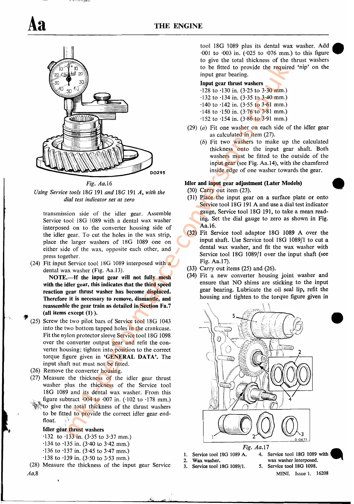
Fig.
Aa.I7
1.
Service tool 18G 1089 A. 4. Service tool 18G 1089 with
•..
2. Wax washer. wax washer interposed.
3. Service tool 18G 1089/1.
5.
Service tool 18G 1098.
MINI. Issue
1.
16208
tool 18G
1089
plus its dental wax washer.
Add.
·001
to ·003 in. (,025 to ·076 mm.)
to
this figure '_
to give the total thickness
of
the thrust washers
to be fitted to provide the required
'nip'
on
the
input gear bearing.
Input gear thrust washers
·128 to ·130 in. (3,25 to 3·30 mm.)
·132
to
·134 in. (3,35
to
3·40 mm.)
·140 to ·142 in. (3,55 to
3·61
mm.)
·148 to ·150 in. (3,76 to
3·81
mm.)
·152 to ·154 in. (3,86 to
3·91
mm.)
(29)
(a)
Fit
one washer
on
each side
of
the idler gear
as calculated in item (27).
(b)
Fit
two washers to make
up
the calculated
thickness onto the input gear shaft. Both
washers must be fitted
to
the outside
of
the
input gear (see Fig. Aa.14), with the chamfered
inside edge
of
one washer towards the gear.
•
•
Idler and input gear adjustment (Later Models)
(30) Carry
out
item (23).
(31) Place the input gear
on
a surface plate
or
onto
Service too118G
191
A and use a dial test indicator
gauge, Service tool 18G 191,
to
take a mean read-
ing. Set the dial gauge to zero as shown
in
Fig.
Aa.16.
(32)
Fit
Service tool
adaptor
18G 1089 A over the
input shaft. Use Service tool 18G 1089/1
to
cut
a
dental wax washer,
and
fit the wax washer with
Service tool 18G 1089/1 over the input shaft (see
Fig. Aa.17).
(33) Carry
out
items (25)
and
(26).
(34)
Fit
a new converter housing
joint
washer
and
ensure
that
NO
shims are sticking
to
the input
gear bearing. Lubricate the oil seal lip, refit the
housing and tighten
to
the torque figure given in
.~
\~
~)-vvr,
\ \
, 5
_?}J
- /
C'
-
~
-l~
-1~
:
..
:;:\)1
(\
fJ
~
~
)~~~~.\~~\~.b
-
\
(~q~\~
/00
(~l1C
~,~{~)
4
~!U1()/1
.
~2003
D
0671
Fig. Aa.16
Using Service tools
18G
191
and 18G
191
A,
with the
dial test indicator set at zero
transmission side
of
the idler gear. Assemble
Service tool 18G
1089
with a dental wax washer
interposed
on
to the converter housing side
of
the idler gear. To cut the holes in the wax strip,
place the larger washers
of
18G
1089
one on
either side
of
the wax, opposite each other, and
press together.
(24)
Fit
input Service tool 18G
1089
interposed with a
dental wax washer (Fig. Aa.13).
NOTE.-If
the input gear will not fully mesh
with the idler gear, this indicates that the third speed
reaction gear thrust washer has become displaced.
Therefore
it
is necessary to remove, dismantle, and
reassemble the gear train as detailed in Section Fa.7
1f/t
(all items except
(1)
).
(25)
Screw the two pilot bars
of
Service tool 18G
1043
into the two bottom tapped holes in the crankcase.
Fit
the nylon protector sleeve Service
tool18G
1098
over the converter output gear and refit the con-
verter housing; tighten into position to the correct
torque figure given in
'GENERAL DATA'. The
input shaft nut must not be fitted.
(26)
Remove the converter housing.
(27) Measure the thickness
of
the idler gear thrust
washer plus the thickness
of
the Service tool
18G
1089
and
its dental wax washer.
From
this
;;.:'/,
'.
figure subtract ·004 to ·007 in. ('102 to
·178
mm.)
~~~),to
give the total thickness
of
the thrust washers
to
be fitted to provide the correct idler gear end-
float. .
Idlerg~ar
thrust washers
·132 to
·133
in. (3,35 to 3·37 mm.)
·134
to
·135 in. (3'40 to 3·42 mm.)
·136 to ·137 in. (3'45 to 3·47 mm.)
·138
to
·139 in. (3,50 to 3·53 mm.)
(28)
Measure the thickness
of
the input gear Service
Aa.8
\}.
;
..
mk1-performance-conversions.co.uk