THE ENGINE
;1
•
Refitting
(16) Immerse the front main bearing cap moulded
rubber oil seal
in
oil
and
fit with the lip facing the
rear
of
the engine.
(17)
Fit
the rubber sealing ring
on
to the main oil
strainer pipe
and
fit new gaskets to the trans-
mission case.
(18) Lower the engine on to the transmission. Ensure
that the moulded rubber seal is correctly located
.•
Tighten the set screws
and
nuts as the transmission
__
is
being lowered in position.
MINI.
Issue
2.
16208
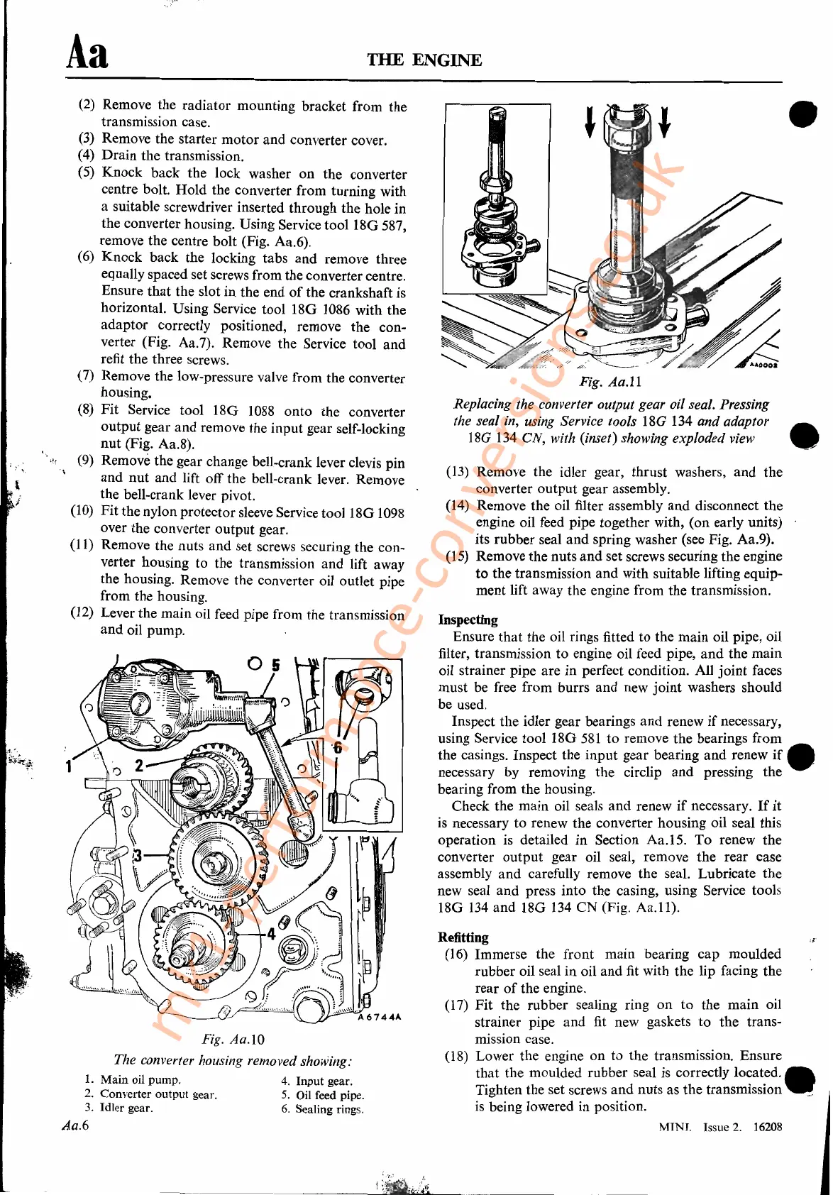
Fig.
Aa.ll
Replacing the converter output gear oil seal. Pressing
the seal in, using Service tools
18G
134
and adaptor •
18G
134
eN, with (inset) showing exploded view
(13)
Remove the idler gear, thrust washers,
and
the
converter output gear assembly.
(14) Remove the oil filter assembly
and
disconnect the
engine oil feed pipe together with, (on early units)
its rubber seal and spring washer (see Fig. Aa.9).
(15) Remove the nuts
and
set screws securing the engine
to
the transmission and with suitable lifting equip-
ment lift away the engine from the transmission.
Inspecting
Ensure that the oil rings fitted to the main oil pipe, oil
filter, transmission to engine oil feed pipe,
and
the main
oil strainer pipe are
in
perfect condition. All
joint
faces
must be free from burrs and new
joint
washers should
be used.
Inspect the idler gear bearings
and
renew
if
necessary,
using Service tool 18G
581
to
remove the bearings from
the casings. Inspect the input gear bearing and renew
if.
necessary by removing the circ1ip and pressing the
bearing from the housing.
Check the main oil seals and renew
if
necessary.
If
it
is
necessary to renew the converter housing oil seal this
operation is detailed in Section Aa.15.
To
renew the
converter output gear oil seal, remove the rear case
assembly and carefully remove the seal. Lubricate the
new seal and press into the casing, using Service tools
18G
134
and
18G
134
CN
(Fig.
Aa.1l).
Aa
Fig. Aa.IO
The converter housing removed showing:
1.
Main
oil pump.
4.
Input
gear.
2.
Converter
output
gear.
5.
Oil feed pipe.
3.
Idler
gear.
6.
Sealing rings.
Aa.6
(2)
Remove the radiator mounting bracket from the
transmission case.
(3) Remove the starter motor and converter cover.
(4) Drain the transmission.
(5) Knock back the lock washer
on
the converter
centre bolt. Hold the converter from turning with
a suitable screwdriver inserted through the hole in
the converter housing. Using Service
tool18G
587,
remove the centre bolt (Fig. Aa.6).
(6) Knock back the locking tabs
and
remove three
equally spaced set screws from the converter centre.
Ensure
that
the slot
in
the end
of
the crankshaft is
horizontal. Using Service tool 18G
1086
with the
adaptor correctly positioned, remove the con-
verter (Fig. Aa.7). Remove the Service tool and
refit the three screws.
(7) Remove the low-pressure valve from the converter
housing.
(8)
Fit
Service tool
l8G
1088
onto the converter
output gear and remove the input gear self-locking
nut (Fig. Aa.8).
"~
(9) Remove the gear change bell-crank lever
c1evis
pin
and
nut
and lift off the bell-crank lever. Remove
the bell-crank lever pivot.
(10)
Fit
the nylon protector sleeve Service tool 18G
1098
over the converter output gear.
(11) Remove the nuts and set screws securing the con-
verter housing to the transmission and lift away
the housing. Remove the converter oil outlet pipe
from the housing.
(12) Lever the main oil feed pipe from the transmission
and
oil pump.
mk1-performance-conversions.co.uk