THE
ENGINE
•
•
MINI. Issue
1.
4908
-r--r
-'
1
--tf'f
Id
----+-:,.
-,IY
I
I1
1'1
i
'r---H----t
I,
, !
I1
I
I
I
G-l.
~
, . I
f----"F
"
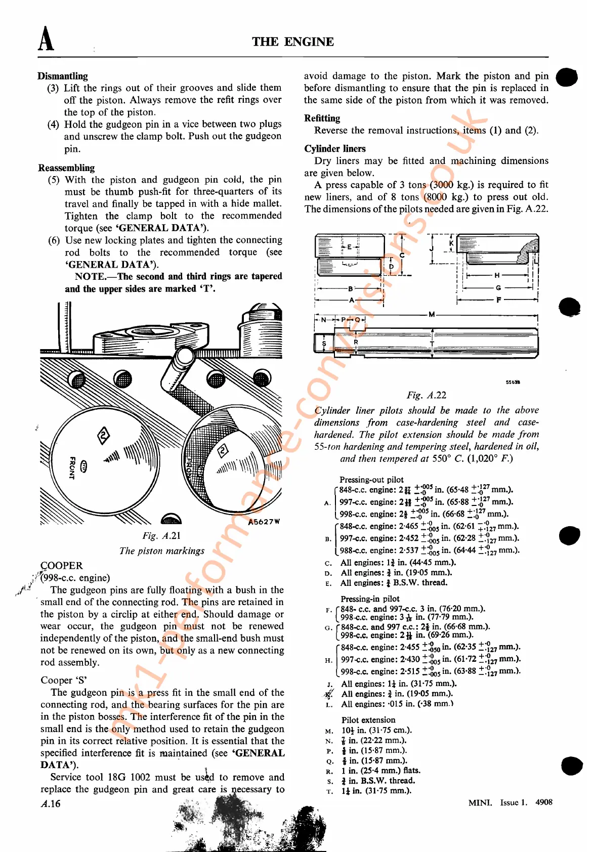
Pressing-out pilot
f
848-C.C.
engine:
2H
!:gosin. (65'48
~:A27
mm.).
A. 997-c.c. engine:
2B
!:gos
in. (65,88 !:A
27
mm.).
L998-c.c. engine: 21
.!:gos
in. (66'68
~:A27
mm.).
r
848-C.C.
engine: 2'465 ::::80sin. (62,61
+:?27
mm.). •
B.
997-c.c. engine: 2·452 !:805 in. (62'28
~:?27
mm.).
L988-e.c. engine: 2'537
::::805
in. (64'44
::::?27
mm.).
c.
All engines:
li
in. (44'45 mm.).
D.
All engines: i in. (19'05 mm.).
E. All engines: i B.S.W. thread.
Pressing-in pilot
F.
(848~
c.c.
an~
997-c.c: 3 in. (76'20 mm.).
998-c.c. engme: 3n m. (77,79 mm.).
G.
(848-C.C. and. 997 c.c.: 21 in. (66'68 mm.).
998-e.c. engme:
2*
m. (69'26 mm.).
[
848-c.C.
engine: 2·455
~:g50
in. (62'35
::::?27
mm.).
H.
997-c.c. engine: 2·430
.!~05
in. (61'72
~:~27
mm.).
998-c.c.
engine: 2·515
::::805
in. (63,88 .!:?27 mm.).
J.
All engines:
It
in. (31'75 mm.).
,tI. All engines: i in. (19,05 mm.).
~.
All engines: ·015 in. (,38
mm.)
Pilot extension
M.
lOt in. (31'75 cm.).
N.
i in. (22,22 mm.).
P.
1 in. (15,87 mm.).
Q.
1 in. (15'87 mm.). •
R.
1 in. (25'4
mm.)
flats. .
s. i in. B.S.W. thread.
T.
11
in. (31'75 mm.).
li
i;
---r
~E~
'j-;;;-i;;=="
==':
=::::IitT C
:
~;;;-CC·_=i..,,_:;_·..J=-=!-LI_1_
,I
:~B~:
:
A-..l
1 I
Fig. A.22
Cylinder liner pilots should be made to the above
dimensions from case-hardening steel and case-
hardened. The pilot extension should be made from
55-ton hardening and tempering steel, hardened
in
oil,
and then tempered at 550
0
C. (1,020
0
F.)
5Sbil
Fr--.-N-=+:-,.-p-
__
.-:
-Q-.j:-------M
----------.jl
~-,-'.
-t~~::d
avoid damage
to
the piston.
Mark
the
piston
and
pin
before dismantling
to
ensure
that
the
pin
is replaced
in
the same side
of
the piston
from
which
it
was removed.
Refitting
Reverse the removal instructions, items (1)
and
(2).
Cylinder liners
Dry
liners
may
be fitted
and
machining dimensions
are given below.
A press capable
of
3 tons (3000 kg.) is required to fit
new liners,
and
of
8 tons (8000 kg.)
to
press
out
old.
The dimensions
of
the pilots needed are given in Fig. A.22.
(5) With the piston
and
gudgeon pin cold, the pin
must be
thumb
push-fit for three-quarters
of
its
travel
and
finally be
tapped
in with a hide mallet.
Tighten
the
clamp
bolt
to
the recommended
torque (see
'GENERAL
DATA').
(6) Use new locking plates
and
tighten the connecting
rod
bolts
to
the recommended torque (see
'GENERAL
DATA').
NOTE.-The
second and third rings are tapered
and the upper sides are marked
'T'.
A
Dismantling
(3) Lift the rings
out
of
their grooves
and
slide them
off the piston. Always remove the refit rings over
the
top
of
the piston.
(4)
Hold
the gudgeon pin in a vice between two plugs
and
unscrew the clamp bolt. Push
out
the gudgeon
pin.
Reassembling
Fig.
A.21
The piston markings
COOPER
;;lr998-c.c. engine)
j£l
The
gudgeon pins are fully floating with a bush in the
, - small
end
of
the connecting rod. The pins are retained in
the piston by a circlip
at
either end. Should damage
or
wear occur, the gudgeon pin
must
not
be renewed
independently
of
the piston,
and
the small-end bush
must
not
be renewed
on
its own,
but
only as a new connecting
rod assembly.
Cooper'S'
The gudgeon pin is a press fit in the small
end
of
the
connecting rod,
and
the
bearing surfaces for the
pin
are
in
the piston bosses.
The
interference fit
of
the pin in the
small
end
is
the
only
method
used
to
retain the gudgeon
pin
in
its correct relative position.
It
is essential
that
the
specified interference fit is maiJ:?tained (see
'GENERAL
DATA').
Service
tool
180
1002
must
be
us~
to
remove
and
replace the gudgeon pin
and
great care is ecessary
to
A.16
mk1-performance-conversions.co.uk