E
THE
CLUTCH
(5) Unscrew the three driving
Pins..
(6) Unscrew the nuts
of
the Service tool
180
304
M,
gradually releasing the housing. Remove
the
housing
and
the springs.
-------
f:/~F====:__-------17
:
===i5iit--=====18
19
20
21
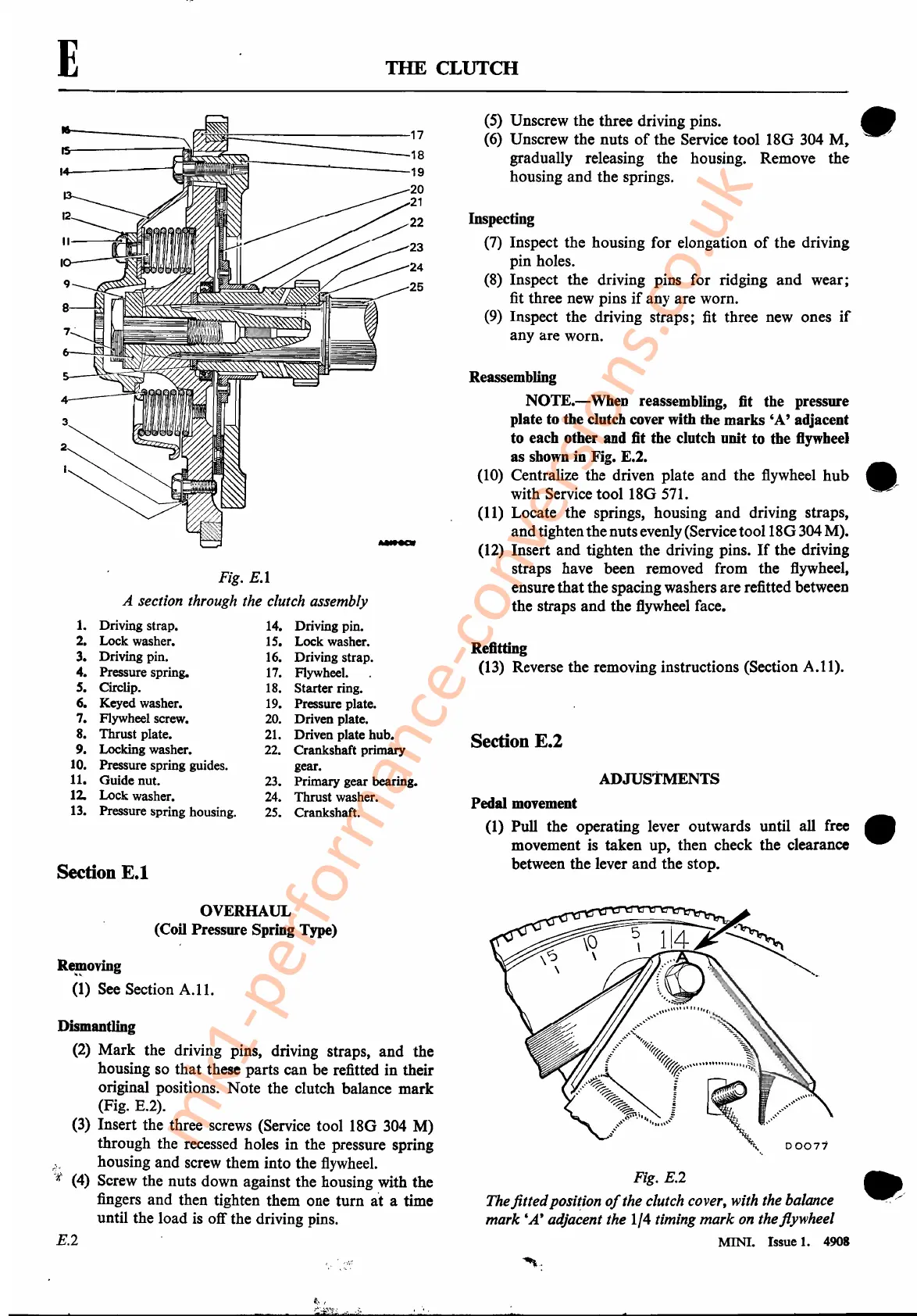
Fig.
E.l
A section through the clutch assembly
1.
Driving strap.
14.
Driving pin.
2. Lock washer.
15.
Lock washer.
3. Driving pin.
16.
Driving strap.
4. Pressure spring.
17.
Flywheel.
S.
Circlip.
18.
Starter ring.
6. Keyed washer.
19.
Pressure plate.
7. Flywheel screw.
20.
Driven plate.
8. Thrust plate.
21.
Driven plate hub.
9. Locking washer.
22.
Crankshaft primary
10.
Pressure spring guides. gear.
11. Guide nut.
23.
Primary gear bearing.
12.
Lock washer.
24.
Thrust washer.
13.
Pressure spring housing.
25.
Crankshaft.
Section
E.l
OVERHAUL
(Coil Pressure Spring Type)
Re~oving
(1) See Section
A.l!.
Dismantling
(2)
Mark
the driving pins, driving straps,
and
the
housing so
that
these parts can be refitted in their
original positions. Note the clutch balance
mark
(Fig. E.2).
(3) Insert the three screws (Service tool
180
304 M).
through the recessed holes in the pressure spring
housing
and
screw them into the flywheel.
(4) Screw the nuts down against the housing with the
fingers
and
then tighten them one
turn
a"t
a time
until the load is off the driving pins.
E.2
Inspecting
(7) Inspect the housing for elongation
of
the driving
pin holes.
(8) Inspect the driving pins for ridging
and
wear;
fit three new pins
if
any are worn.
(9) Inspect
the
driving straps; fit three new ones
if
any are worn.
Reassembling
NOTE.-When
reassembling, fit the pressure
plate to the clutch cover with the marks
'A'
adjacent
to each other and fit the clutch unit to the flywheel
as shown in Fig. E.2.
(10) Centralize the driven plate
and
the flywheel
hub
with Service tool
180
571.
(11) Locate the springs, housing
and
driving straps,
and
tightenthenutsevenly(Service tool
180
304 M).
(12) Insert
and
tighten the driving pins.
If
the driving
straps have been removed from the flywheel,
ensure
that
the spacing washers are refitted between
the straps
and
the flywheel face.
Refitting
(13) Reverse the removing instructions (Section A.11).
Section E.2
ADJUSTMENTS
Pedal
movement
(1) Pull the operating lever outwards· until all free
movement is taken up, then check the clearance
between the lever
and
the stop.
Fig. E.2
The
fitted
position
of
the clutch cover, with the balance
mark
'A'
adjacent the 1/4 timing
mark
on theflywhee/
MINI. Issue
1.
4908
•
,..
""
.....
•
mk1-performance-conversions.co.uk