THE STEERING
J
COOPER
Carry
out
the
instructions detailed above
and
also:
(15) Disconnect the
gear
lever extension from
the
floor.
(16) Remove the exhaust pipe
and
silencer (Section
A.3).
Dismantling
(17) Disconnect the tie-rods from the steering-arms.
(18) Remove the
rubber
gaiters.
(19) Remove
the
damper
cover plate, yoke,
and
spring(s).
(20) Remove the pinion shaft tailbearingretainingplate,
shims,
thrust
washer, bearing
and
bearing race,
and
withdraw the pinion. Extract the
top
bearing race,
bearing,
and
thrust
washer
from
behind
the
rack
teeth.
(21) Extract
the
pinion shaft oil seal.
(22) Use Service tool 18G 707
to
unscrew the ball
housing
and
release the tie-rod, ball seat
and
tension spring. Remove the second tie-rod.
(23) Withdraw the
rack
from the pinion
end
of
the
rack
housing
to
obviate damage
to
the felt
or
'Vulkollan'
bush
fitted in the opposite
end
of
the
rack
housing.
(24) Remove the bush securing screw from the rack
housing, lever
the
felt
bush
at
its
joint
and
extract
it.
The
felt
bush
metal sleeve
must
be removed
if
a
plastic ('Vulkollan')
bush
is to be fitted as a re-
placement for the felt bush.
.Inspecting
(25) Clean all parts
and
examine for wear, particularly
the
rack
and
pinion teeth,
and
the
rubber
gaiters.
Fit
new
parts
where necessary.
AS385AW
Fig.
1.4
A section throllgh the steering pinion and rack damper
(Ist
type)
A.
Take a feeler gauge measurement and fit the pinionend cover
with shims
to
the value
of
the measurement minus
·001
to
·003 in. ('025
to
·076 mm.) before fitting the damper yoke (C).
B. Measure the gap
and
fit
shims.
c.
Damper
yoke.
J.4
•
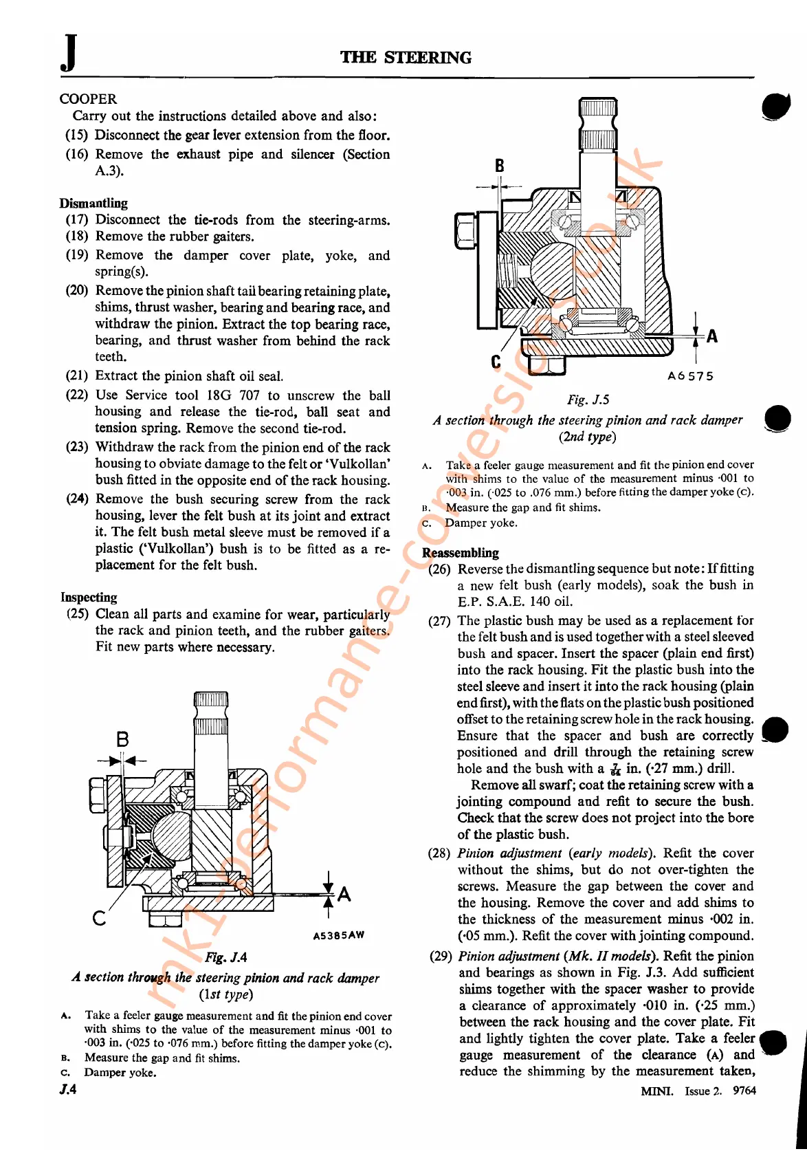
Fig.
J.5
A section through the steering pinion and rack damper •
(2nd type)
A.
Take a feeler gauge measurement and fit the pinion end cover
with shims
to
the value
of
the measurement minus '001 to
·003 in. ('025
to
.076 mm.) before fitting the damper yoke
(c).
D. Measure the gap and
fit
shims.
c.
Damper
yoke.
Reassembling
(26) Reverse thedismantling sequence
but
note:
Iffitting
a new felt
bush
(early models),
soak
the
bush in
E.P. S.A.E. 140 oil.
(27) The plastic
bush
may be used as a replacement for
the felt
bush
and
is usedtogetherwith a steel sleeved
bush
and
spacer. Insert
the
spacer (plain
end
first)
into
the
rack housing.
Fit
the
plastic
bush
into
the
steel sleeve
and
insert
it
into
the
rack
housing (plain
end
first), withtheflats
on
theplastic
bush
positioned
offset
to
the retainingscrewhole in the
rack
housing. •
Ensure
that
the
spacer
and
bush
are
correctly _
positioned
and
drill
through
the
retaining screw
hole
and
the
bush
with a
ll.
in. (,27 mm.) drill.
Remove all swarf;
coat
the
retaining screw with a
jointing
compound
and
refit
to
secure
the
bush.
Check
that
the
screw does
not
project
into
the
bore
of
the
plastic bush.
(28) Pinion adjustment (early models). Refit
the
cover
without
the
shims,
but
do
not
over-tighten the
screws. Measure the
gap
between
the
cover
and
the housing. Remove the cover
and add
shims
to
the thickness
of
the measurement minus ·002 in.
(,05 mm.). Refit
the
cover with
jointing
compound.
(29) Pinion adjustment
(Mk.
11
models). Refit
the
pinion
and
bearings as shown
in
Fig. J.3.
Add
sufficient
shims together with the spacer washer
to
provide
a clearance
of
approximately ·010 in. (,25 mm.)
between
the
rack
housing
and
the
cover plate.
Fit
and
lightly tighten the cover plate.
Take
a
feeler.
gauge measurement
of
the
clearance
(A)
and'
reduce the shimming
by
the
measurement taken,
MINI. Issue
2.
9764
mk1-performance-conversions.co.uk