K
THE
FRONT SUSPENSION
Section K.9
SWIVEL
HUB
OUTER
OIL
SEAL
The following instructions will permit a leaking outer
seal
to
be
replaced when the driving flange is removed.
NOTE.-A
bearing overhaul will still require swivel hub
removal as in Section K.3.
•
(4) Remove the drive shaft
nut
and
assemble the
Service tool 18G 304
and
180
304 F
to
the drive •
flange. -=-
(5) Replace the Service tool centre screw with
adaptor
180304
P
and
use the impulse extractor
180284
to remove the flange.
(6) Should the outer bearing inner race come away
with the driving flange,
it
can
be removed with
Service tool
180
705
and
adaptor
180705
B.
Fig. K.6
A section through the swivel hub ball joints. Take
feeler gauge measurements at the positions indicated
without the locking washers fitted and without the seat
springfitted to the lower balljoint
Section K.7
DISPLACER
UNITS
(Hydrolastic Suspension)
Removing
(1)
Jack
up the car
and
remove the
road
wheel.
(2) Depressurize
and
evacuate the Hydrolastic system
(see Section H.7).
(3) Release the displacer strut dust seal from the nylon
seat
and
extract the strut from the displacer unit.
(4) Disconnect the displacer hose from the union on
the engine bulkhead.
(5) Remove the suspension
top
arm
(see Section
KA).
(6) Push the displacer upwards
and
remove two screws
to
release the displacer bracket from inside the
sub-frame tower.
(7) Rotate the displacer anti-clockwise
and
withdraw
it from the sub-frame.
Refitting
(8) Reverse the removal instructions.
(9) Rotate the displacer clockwise
to
lock it into the
registers
on
the locating plate.
(10) Lubricate the strut ball end
and
the nylon seat
with Dextragrease Super
O.P.
and
make sure the
dust seal is fitted over the lip
of
the nylon cup.
(11)
Evacuate
and
pressurize the system (see Section
H.7).
Section K.8
UPPER
SUSPENSION
ARMS
(Hydrolastic Suspension)
RemoTa}
Depressurize the Hydrolastic system as in Section H.7
and follow the instruction in
KA
for
arm
removal.
K.6
Removing
(1) Remove the hub cover, extract the split pin,
and
slacken the drive shaft nut.
(2) Slacken the wheel nuts
and
jack
up the vehicle.
(3) Take off the
road
wheel
and
remove the brake-
drum.
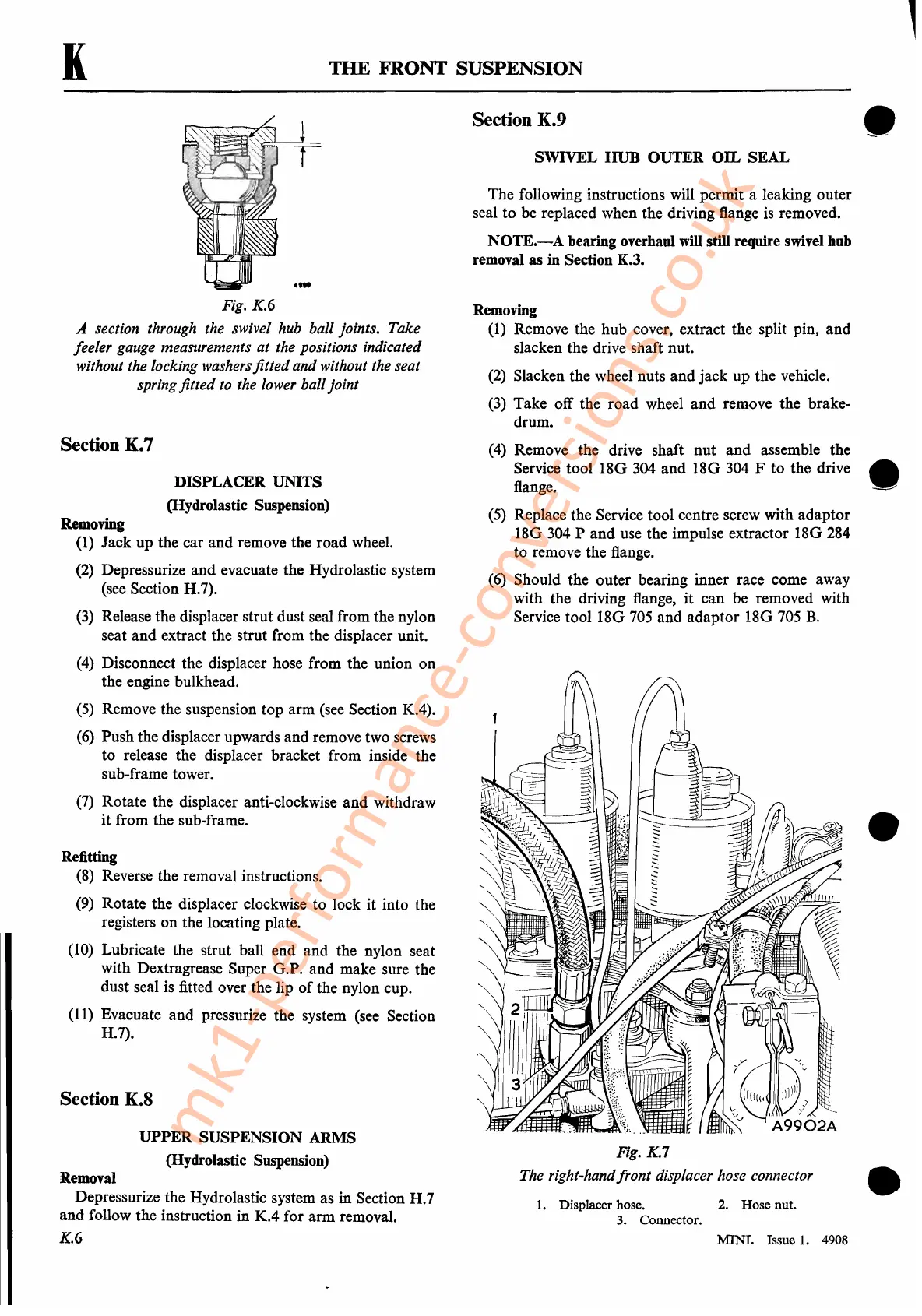
Fig. K.7
The right-hand
front
displacer hose connector
1.
Displacer hose.
2.
Hose nut.
3.
Connector.
MINI. Issue
1.
4908
•
•
mk1-performance-conversions.co.uk
 Loading...


