THE
BRAKING SYSTEM
•
••
J
L
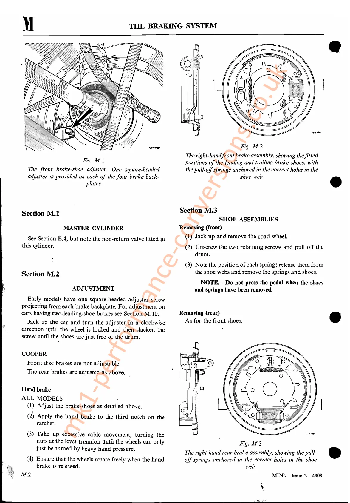
Fig.
M.2
The right-hand/ront brake assembly, showing
thefitted
positions
of
the leading and trailing brake-shoes, with
the
pull-off
springs anchored
in
the correct holes in the
shoe web
Fig.
M.I
The front brake-shoe adjuster. One square-headed
adjuster is provided on each
of
the four. brake back-
plates
M
Section
M.t
MASTER CYLINDER
See
Section EA, but note the non-return valve fitted
i.n
this cylinder.
Section M.2
ADJUSTMENT
Early models have one square-headed adjuster screw
projecting from each brake backplate.
For
adjustment on
cars having two-leading-shoe brakes
see
Section M.IO.
Jack up the car and turn the adjuster in a clockwise
direction until the wheel
is
locked and then slacken the
screw until the shoes are just free
of
the drum.
Section M.3
SHOE
ASSEMBLIES
Removing (front)
(1) Jack up and remove the road
whe~1.
(2)
Unscrew the two retaining screws and pull off the
drum.
(3)
Note the position
of
each spring; release them from
the shoe webs and remove the springs
and
shoes
..
NOTE.-Do
not press the pedal
when
the shoes
and springs have been removed.
Removing (rear)
As for the front shoes.
•
COOPER
Front disc brakes are not adjustable.
The rear brakes are adjusted
as
above.
Hand brake
ALL MODELS
(1) Adjust the brake-shoes as detailed above.
(2)
Apply the hand brake to the third notch on the
ratchet.
(3) Take up excessive cable movement, turning the
nuts at the lever trunnion
l1ntil
the wheels can only
just be turned by heavy hand pressure.
(4)
Ensure that the wheels rotate freely when the hand
brake
is
released.
Fig.
M.3
The right-hand rear brake
assembly~
showing the pull-
off
springs anchored in the correct holes in the shoe
web
•
M.2 MINI. Issue
1.
4908
~:
.;:
..
,,~.,.-":;;"
mk1-performance-conversions.co.uk