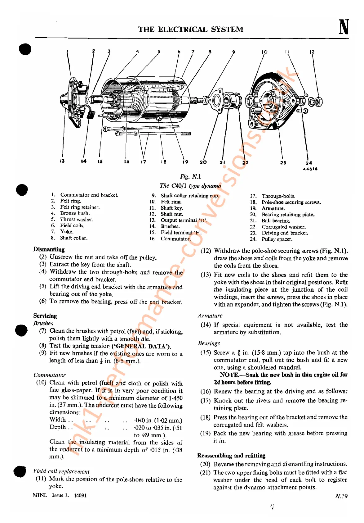
1.
Commutator end bracket.
2.
Felt ring.
3.
Felt ring retainer.
4. Bronze bush.
5.
Thrust washer.
6.
Field coils.
7. Yoke.
8.
Shaft collar.
THE
ELECTRICAL SYSTEM
Fig.
N.1
The C40j1 type dynamo
9.
Shaft collar retaining cup.
10.
Felt ring.
11.
Shaft key.
12.
Shaft nut.
13.
Output terminal
'D'.
14.
Brushes.
15.
Field terminal
'P'.
16.
Commutator.
N
24
"4616
23
17. Through-bolts.
18.
Pole-shoe securing screws.
19. Armature.
20.
Bearing retaining plate.
21. Ball bearing.
22.
Corrugated washer.
23.
Driving end bracket.
24.
Pulley spacer.
21
20
19
.8
17
15
••
13
•
•
Field coil replacement
(11)
Mark
the
position
of
the pole-shoes relative
to
the
yoke.
MINI. Issue
1.
14091
(12) Withdraw
the
pole-shoe securing screws (Fig.
N.I).
draw
the
shoes
and
coils from
the
yoke
and
remove
the
coils from
the
shoes.
(13)
Fit
new coils
to
the
shoes
and
refit
them
to
the
yoke with the shoes
in
their original positions. Refit
the
insulating piece
at
the
junction
of
the
coil
windings, insert
the
screws, press
the
shoes
in
place
with
an
expander,
and
tighten
the
screws (Fig.
N.l).
Reassembling and refitting
(20) Reverse
the
removing
a.nd
dismantling instructions.
(21) The two
upper
fixing bolts
must
be
fitted with a flat
washer
under
the
head
of
each
bolt
to
register
against
the
dynamo attachment points.
Armature
(14)
If
special equipment is
not
available, test
the
armature
by
substitution.
Bearings
(15) Screw a i in. (15,8 mm.)
tap
into
the
bush
at
the
commutator
end, pull
out
the
bush
and
fit a new
one, using a shouldered mandrel.
NOTE.-Soak
the new bush in thin engine oil for
24 hours before fitting.
(16) Renew
the
bearing
at
the
driving
end
as follows:
(17)
Knock
out
the rivets
and
remove
the
bearing re-
taining plate.
(18) Press
the
bearing
out
of
the
bracket
and
remove
the
corrugated
and
felt washers.
(19)
Pack
the
new bearing with grease before pressing
it
in.
N.19
·040 in. (1,02 mm.)
·020
to
·035 in. (,51
to
·89 mm.).
Clean the insulating material from
the
sides
of
the undercut
to
a minimum
depth
of
·015 in. (,38
mm.).
Commutator
(10) Clean with petrol (fuel)
and
cloth
or
polish with
fine glass-paper.
Ifit
is
in
very
poor
condition
it
may be skimmed
to
a minimum diameter
of
1·450
in. (37 mm.).
The
undercut must have
the
following
dimensions:
Width
..
Depth
..
Servicing
Brushes
(7) Clean
the
brushes with petrol (fuel) and,
if
sticking,
polish
them
lightly with a
smooth
file.
(8) Test the spring tension
('GENERAL
DATA').
(9)
Fit
new brushes
if
the
existing ones are
worn
to
a
length
of
less
than!
in. (6'5 mm.).
Dismantling
(2) Unscrew the
nut
and
take off the pulley.
(3) Extract the key from
the
shaft.
(4) Withdraw the two through-bolts
and
remove the
commutator
end bracket.
(5) Lift the driving end bracket with
the
armature
and
bearing
out
of
the yoke.
(6)
To
remove the bearing, press off the
end
bracket.
•
•
mk1-performance-conversions.co.uk



 To Next Page