A
THE ENGINE
from the pressure spring housing. When a dia- •
phragm clutch
is
fitted, release the spring retainer '
to detach the thrust plate.
(11)
Bring Nos. 1 and 4 pistons
to
T.D.C. to prevent
the primary gear
'C'
washer from falling and being
wedged behind the flywheel. With the crankshaft
in any other position this could happen and result
in damage as the flywheel
is
withdrawn.
(12)
Tap up the locking washer
and
slacken the flywheel
retaining screw three or four threads. Use Service
tools
l8G
304 and 18G 304 M
to
free the flywheel
from the taper on the crankshaft. Remove the tool
as
soon as the flywheel
is
free.
(13)
Unscrew the flywheel retaining screws and take
off the driving washer.
(14) Withdraw the flywheel and clutch together.
(15)
Dismantle the clutch as described in
S~ction
E.l.
NOTES:
'If
•
(A)
As
the flywheel is pulled from the shaft,
01
rom
the annulus behind the flywheel oil seal may spill
down the face
of
the flywheel onto the clutch driven
plate. Look out for this when dismantling
to
avoid assuming
that
the oil has passed the seal
during normal running.
(B)
In
early engines a rubber plug was fitted into the
rear end
of
the crankshaft as
an
added precaution
against oil leaking past the normal brass taper plug.
An improved brass plug
is
nowfitted
and
the rubber
is
discontinued.
(c)
Later engines have non-lubricated bushes
in
the
crankshaft primary gear and the flywheel oil seal
is
not fitted.
Fig.
A.8
The distributor drive with the slot
in
the correct
position and the large offset uppermost
Refitting
(3)
Turn
the crankshaft until No. 1 piston
is
at T.D.C.
on the compression stroke (No. 4 cylinder exhaust
and inlet valves rocking and the 1/4 mark on the
flywheel against the pointer).
(4)
Hold"
the spindle so that the drive slot
is
in the
po~iti6ii"shown
(Fig. A.8) with the large offset
uppermost, and enter the gear. As the gear
engages the camshaft the spindle will turn anti-
clockwise.
(5)
Refit the distributor (Sections B.l and B.2).
Section
A.tt
\ .,
,.,:~
FLYWHEEL
AND
CLUTCH
Removing
(1)
Disconnect the coil (or solenoid) leads and remove
the coil (or solenoid).
(2)
Remove the starter (Section N.3).
(3)
Unhook the clutch lever spring, withdraw the
lever pivot pin, pull the push-rod from the slave
cylinder and remove the lever from the clutch
....
,...
housing.
(4)
Take off the slave cylinder.
(5)
Disconnect the exhaustpipeJmanifold clamp.
(6) Detach the radiator support bracket from the
thermostat housing.
(7)
Unscrew the two nuts and set screws securing the
right-hand engine mounting to the sub-frame side-
member.
(8)
Take out the clutch cover screws.
(9) Raise the engine just enough to allow the removal
of
the clutch cover.
Do
not let the fan blades
damage the radiatol.'.
(10) Remove the three nuts and the clutch thrust plate
A.8
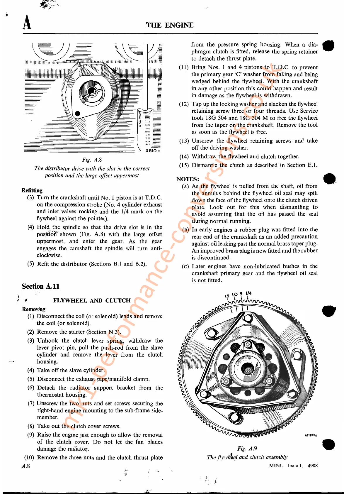
Fig. A.9
,-
The
.flyw~(JJ
and clutch assembly
MINI.
Issue
1.
4908
•
•
mk1-performance-conversions.co.uk