Dismantling
Contact breaker only
(4) Remove the rotor arm and the slotted nylon
low-tension terminal insulator from the distributor
body.
(5) Take
out
the two screws, ease
up
the contact
breaker plate
and
unhook the flexible actuating
link.
Removing
(1)
Turn
the crankshaft until Nos. 1
and
4 pistons are
at
T.D.C., the rotor arm is pointing
to
No. 1
segment inthe cap
and
the points arejust breaking.
(2) Disconnect the low-tension lead from the terminal
on
the side
of
the distributor,
and
the suction
advance pipe from the union.
(3) Take
out
the two set screws securing the clamp
plate
and
pull out the distributor.
Do
not loosen
the clamp plate pinch bolt.
NOTE.-The
position of the driving dog slot. The
distributors on later models have an
'0'
ring oil seal
fitted to the mounting shank.
B
Section
B.l
DISTRIBUTOR
THE
IGNITION SYSTEM
•
.-
1<24268
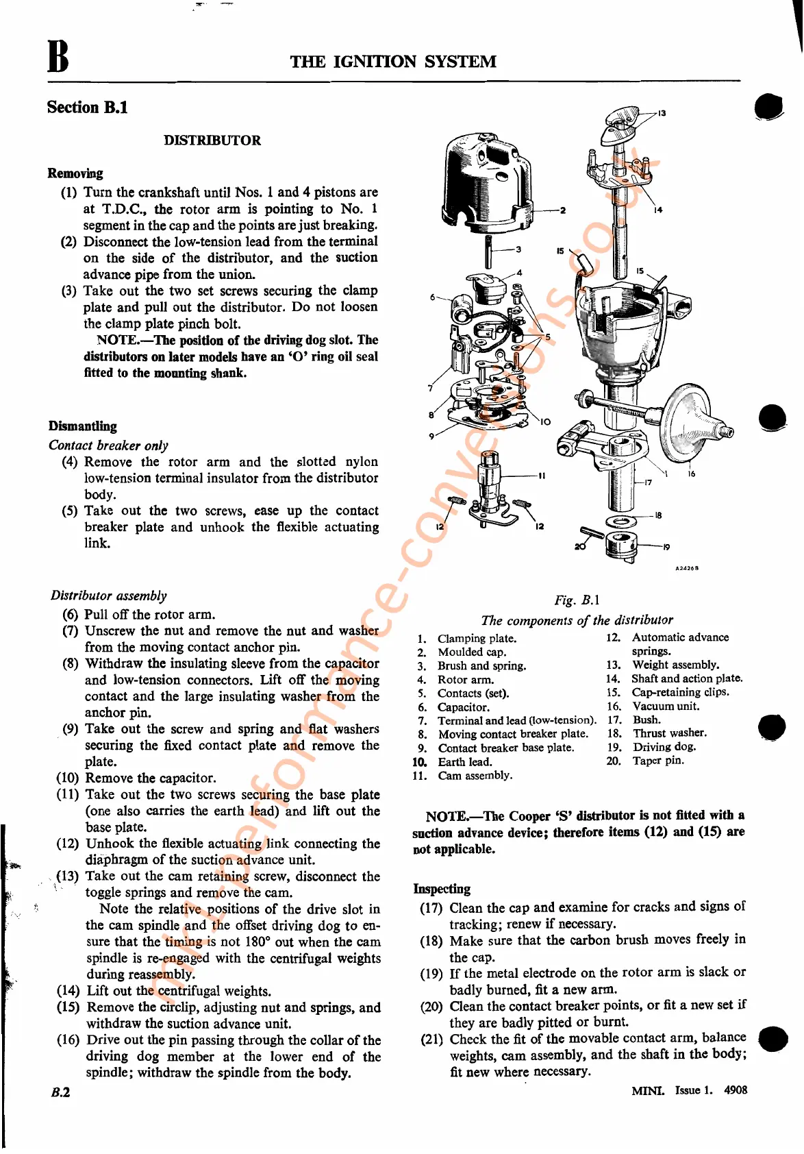
Fig.
B.l
The components
of
the distributor
NOTE.-The
Cooper
'8'
distributor is not fitted with a
suction advance device; therefore items
(12) and (15) are
not applicable.
Inspecting
(17) Clean the cap and examine for cracks
and
signs
of
tracking; renew
if
necessary.
(18) Make sure
that
the carbon brush moves freely in
the cap.
(19)
If
the metal electrode
on
the
rotor
arm
is slack
or
badly burned, fit a new arm.
(20) Clean the contact breaker points,
or
fit a new set
if
they are badly pitted
or
burnt.
(21) Check the fit
of
the movable contact arm, balance
weights,
cam
assembly,
and
the shaft in
the
body;
fit new where necessary.
•
•
12.
Automatic advance
springs.
13.
Weight assembly.
14.
Shaft and action plate.
15.
Cap-retaining clips.
16.
Vacuum unit.
17.
Bush.
18. Thrust washer.
19.
Driving dog.
20.
Taper pin.
1.
Clamping plate.
2.
Moulded cap.
3.
Brush and spring.
4.
Rotor arm.
5.
Contacts (set).
6.
Capacitor.
7. Terminal and lead (low-tension).
8.
Moving contact breaker plate.
9. Contact breaker base plate.
10. Earth lead.
11.
Cam assembly.
Distributor assembly
(6) Pull offthe
rotor
arm.
(7) Unscrew the
nut
and
remove the
nut
and
washer
from the moving contact anchor pin.
(8) Withdraw the insulating sleeve from the capacitor
and
low-tension connectors. Lift off the moving
contact
and
the large insulating washer from the
anchor pin.
(9) Take
out
the screw and spring
and
flat washers
, securing the fixed contact plate
and
remove the
plate.
(10) Remove the capacitor.
(11) Take
out
the two screws securing the base plate
(one also carries the earth lead)
and
lift
out
the
base plate.
(12)
Unhook
the flexible actuating link connecting the
diaphragm
of
the suction advance unit.
,;(13) Take
out
the cam retaining screw, disconnect the
~
. toggle springs
and
remove the cam.
Note the relative positions
of
the drive slot in
the cam spindle
and
the offset driving dog
to
en-
sure that the timing
is
not
180
0
out when the cam
spindle is re-engaged with the centrifugal weights
during reassembly.
(14) Lift out the centrifugal weights.
(15) Remove the circlip, adjusting
nut
and
springs,
and
withdraw the suction advance unit.
(16) Drive
out
the pin passing through the collar
of
the
driving dog member
at
the lower end
of
the
spindle; withdraw the spindle from the body.
B.2
. MINI. Issue
1.
4908
mk1-performance-conversions.co.uk