THE
FUEL SYSTEM
Ba
Section
Da.l
AIR CLEANER
Cars equipped with automatic transmission are fitted
with a larger paper-element-type air cleaner.
Removing
(1)
Unscrew the wing nuts.
(2)
Disconnect the breather hose.
(3)
Lift the air cleaner from the carburetter.
Element replacement
(4)
Remove the cover from the container and lift out
the paper element.
(5)
Wipe all dust deposit from inside the container.
(6)
Fit the new element and refit the cover.
Refitting ,
(7)
Revef,§.~fhe
removal·procedure.
NOTE.~Tlitf
air cleaner intake should be positioned
adjacent
..
~
the exhaust manifold during winter operating
conditifiis in order that the possibility
of
carburetter icing
is reduced to the minimum.
It
is advisable
to
move
the
intake away from the manifold in warmer weather.
Section Da.2
CARBURETTER
(Type HS4)
Description
The HS4 carburetter
is
fitted to an engine equipped
with automatic transmission
The dismantling and reassembling
of
the carburetter
is
as described for the HS2 type in Section D.6.
Removing
(1)
Remove the air cleaner as detailed in Section
Da.l.
(2)
Disconnect the mixture and throttle control cables,
the suction advance pipe, and .the fuel delivery
hose from the carburetter.
(3)
Disconnect the governor control rod
fork
'end
from the throttle lever.
(4) Remove the securing nuts and spring washers and
lift off the carburetter and the cable abutment
plate.
Da.2
•
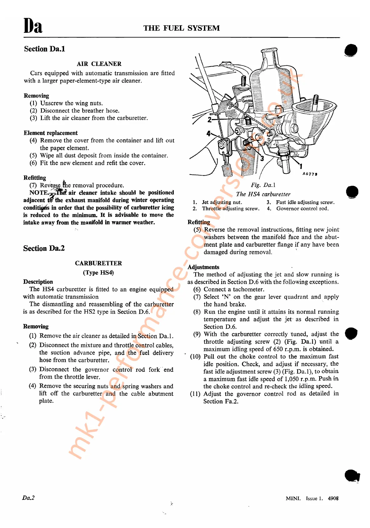
Fig.
Da.l
•
The
HS4
carburetter
...-
1.
Jet adjusting nut. 3. Fast idle adjusting screw.
2.
Throttle adjusting screw. 4. Governor control rod.
Refitting
(5)
Reverse the removal instructions, fitting new
joint
washers between the manifold face and the abut-
ment plate and carburetter flange
if
any have been
damaged during removal.
i
Adjustments
The method
of
adjusting the jet and slow running
is.
as described in Section D.6 with the following exceptions.
(6)
Connect a tachometer.
(7)
Select
'N'
on the gear lever quadrant and apply
the hand brake.
(8)
Run the engine until it attains its normal running:
temperature and adjust the jet· as described in
Section D.6.
(9)
With the carburetter correctly tuned, adjust the •
throttle adjusting screw
(2)
(Fig.
Da.l)
until a
maximum idling speed
of
650
r.p.m.
is
obtained.
(10) Pull out the choke control to the maximum fast
idle position. Check, and adjust
if
necessary,
the
fast idle adjustment screw
(3)
(Fig.
Da.l),
to obtain
a maximum fast idle speed
of
1,050 r.p.m. Push in
the choke control and re-check the idling speed.
(11)
Adjust the governor control rod as detailed in
Section Fa.2.
•
MINI. Issue
1.
4908
mk1-performance-conversions.co.uk