•
THE
AUTOMATIC TRANSMISSION
POWER
FLOW DIAGRAMS (MECHANICAL)
Fa
5.7675
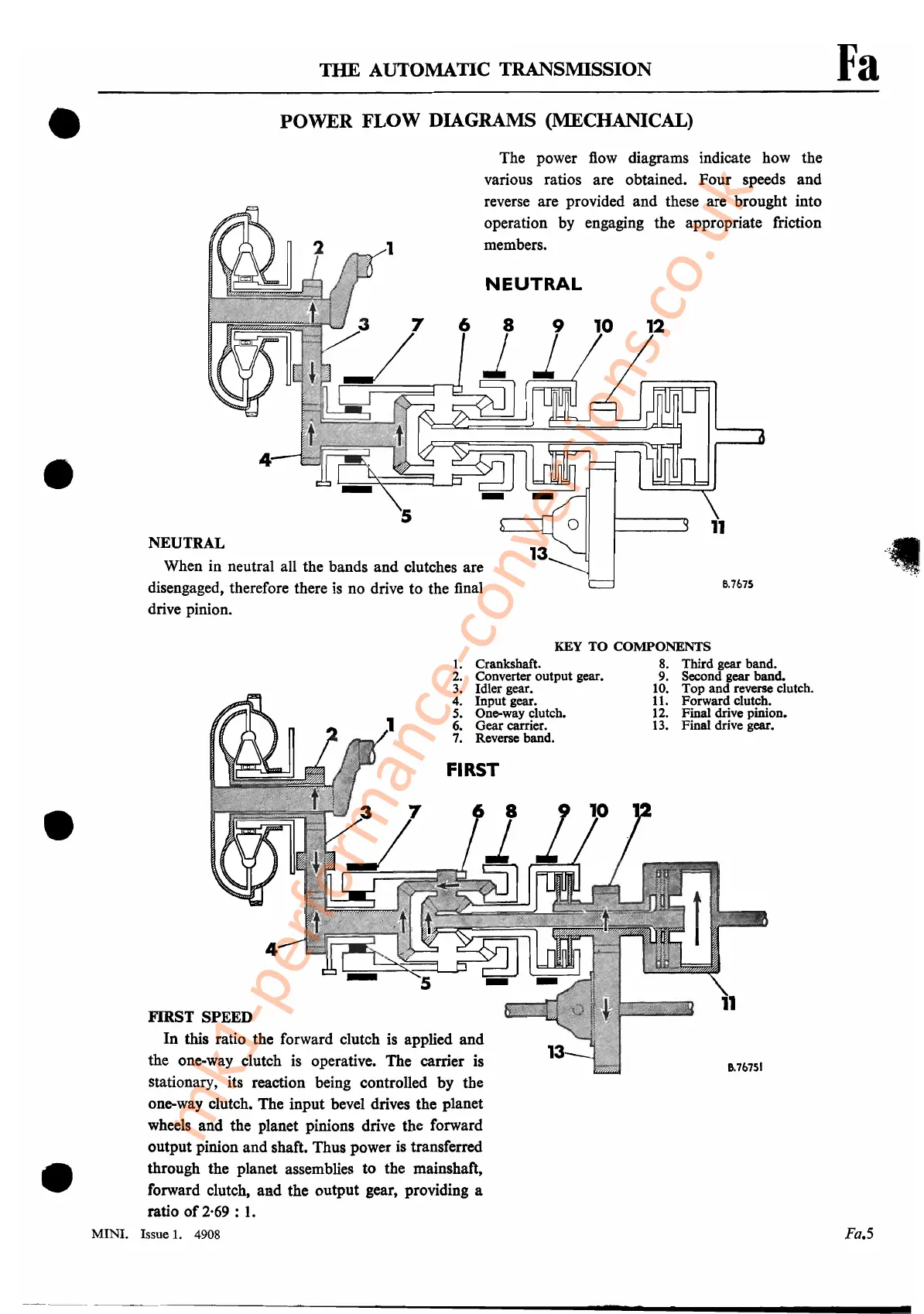
NEUTRAL
NEUTRAL
When in neutral all the bands and clutches are
disengaged, therefore there
is
no drive to the final
drive pinion.
The power
flow
diagrams indicate how the
various ratios are obtained.
Four
speeds and
reverse are provided and these are brought into
operation by engaging the appropriate friction
members.
•
1.
Crankshaft.
2.
Converter output gear.
3.
Idler gear.
4.
Input gear.
5.
One-way clutch.
6.
Gear carrier.
7.
Reverse band.
•
•
FIRST
FIRST SPEED
In this ratio the forward clutch is applied and
the one-way clutch is operative. The carrier is
stationary, its reaction being controlled by the
one-way clutch. The input bevel drives the planet
wheels and the planet pinions drive the forward
output pinion and shaft. Thus power is transferred
through the planet assemblies to the mainshaft,
forward clutch,
aBd
the output gear, providing a
ratio
of
2·69
:
1.
MINI. Issue
1.
4908
KEY
TO
COMPONENTS
8.
Third gear band.
9.
Second gear band.
10.
Top and reverse clutch.
11.
Forward clutch.
12.
Final drive pinion.
13.
Final drive gear.
8.76751
Fa.S
-~-~---~----------------_
......
-.
.....
_---------
mk1-performance-conversions.co.uk