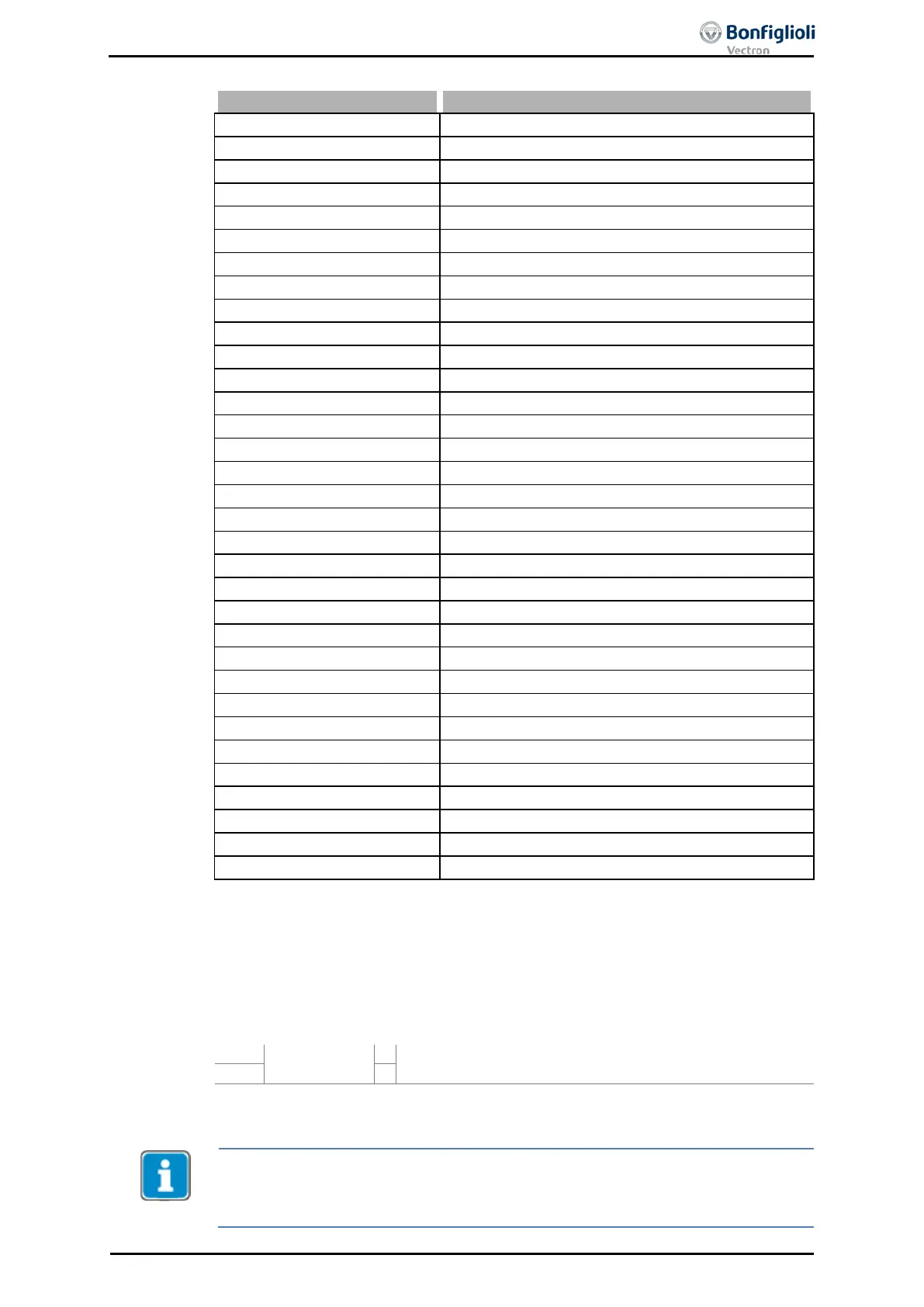
A FFFF FFFF - 1 -
Activate everything
A 0000 FFFF - 2 -
Activate all Warnings
A FFFF 0000 - 3 -
Activate all Controller States
A 0000 0001 Ixt 10 -
Warning Ixt
Warning Heat Sink Temperature
Warning Inside Temperature
A 0000 0040 INIT 16 -
Warning Init
A 0000 0080 MTemp 17 -
Warning Motor Temperature
A 0000 0100 Mains 18 -
Warning Mains Failure
A 0000 0200 PMS 19 -
Warning Motor Protective Switch
A 0000 0400 Flim 20 -
Warning Fmax
Warning Analog Input MFI1A
A 0000 1000 A2 22 -
Warning Analog Input MFI2A
A 0000 2000 Sysbus 23 -
Warning Systembus
A 0000 4000 UDC 24 -
Warning Udc
A 0000 8000 WARN2 25 -
Warning application
A 0001 0000 UDdyn 30 -
Controller Udc Dynamic Operation
A 0002 0000 UDstop 31 -
Controller Shutdown
A 0004 0000 UDctr 32 -
Controller Mains Failure
A 0008 0000 UDlim 33 -
Controller Udc Limitation
Controller Voltage Pre-Control
Controller Torque Limitation
Controller Torque Control
Contr. Intel. Curr. Lim. LT-Ixt
Contr. Intel. Curr. Lim. ST-Ixt
A 0800 0000 Tclim 41 -
Contr. Intel. Curr. Lim. Tc
A 1000 0000 MtempLim 42 -
Contr. Intel. Curr. Lim. Motor Temp.
A 2000 0000 Flim 43 -
Controller Freq. Limitation
The selected warning mask can be read out via parameter Actual Warning Mask
537. The above operation modes of parameter Create Warning Mask 536 are en-
coded in the
Actual Warning Mask 537. The code is calculated by hexadecimal addi-
tion of the individual operation modes and the corresponding abbreviation.
The output of a warning message is signaled.
Warning Mask
Output of a warning message which is activated in Create
Warning Mask
536.
1)
For linking with inverter functions
Parameter Warning 269 and Warning 356 (error environment) show the warnings
independent from the created Warning mask.
Controller Status 275 and Controller Status 355
(error environment)
show the Controller Status independent from the created Warning mask.
06/13 Operating Instructions ACU 189

 Loading...