Access Modular Controller 2 Installing | en 43
Bosch Access Systems V.B. Installation manual 2020-01 | V02 |
4.6.1 Grounding for Host Interface
A 1:
A 2:
A 3:
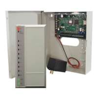
Delivery status
JP1
JP2
JP1
JP2
A
Figure4.14: Location of ground jumper RS-485 host interface
Figure4.15: Location of ground jumper RS-485 host interface
The internal ground of the controller is always connected with the ground of the RS-485 host.
The jumper setting 1 shows the factory settings.
The internal ground of the AMC2-4W is always connected with the ground of the RS-485 host.
The jumper setting 1 shows the factory settings.
The jumper setting A1 shows the factory settings.
Jumper JP1 connects the internal ground of the AMC2-4R4 to the ground of the RS-485 host
interface.
Jumper JP2 manages the signal ground.
The jumper setting A1 shows the factory settings.
Jumper JP1 connects the internal ground of the AMC2-4W to the ground of the RS-485 host
interface.
Jumper JP2 manages the signal ground.
This jumper manages the signal ground.
Settings for jumper JP1:
If the ground conductor and the shield on the host are not connected and:
– no party line exists, the jumper JP1 is set (=A2)
– a party line exists, the jumper JP1 is set at the first device only (=A2)
 Loading...