46 en | Installing Access Modular Controller 2
2020-01 | V02 | Installation manual Bosch Access Systems V.B.
4.7 Connecting Power Supply
Connect the power supply to the POWER 7-pin pluggable screw connector. Refer to
Connecting Diagrams, page 102 for a complete diagram of the power supply connector.
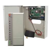
Figure4.21: Location of the power supply connector
Figure4.22: Location of the power supply connector
Figure4.23: Location of the power supply connector
Connect an external power supply (10 - 14 Vdc) for the AMC2 device at pin 1 (positive) and
pin 3 (0 V) of the pluggable screw connector.
If an uninterruptible power supply (UPS) is used, the relay output for power good signals from
the UPS is connected to the following pins:
– pin 4 and 7 for power good AC
– pin 5 and 7 for power good Battery
– pin 6 and 7 for power good DC
 Loading...