68 en | Installing Access Modular Controller 2
2020-01 | V02 | Installation manual Bosch Access Systems V.B.
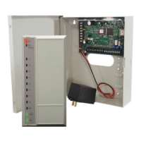
Figure4.53: Connection of an extension module to an AMC2
4.12.1 Addressing
The address of the board is set using a switch on the board’s underside (see Equipment
Configuration, page 16).
The address of the board is set using a switch on the board’s underside (see Equipment
Configuration).
Up to three extension boards (BIS) can be connected to one AMC2 - depending on that the
addresses 1 to 3 can be assigned, only.
Notice!
When configuring the system, ensure that the order of boards in the access control software
corresponds to the addresses you set using this switch.
This order of addressing determines the numbering of the boards’ signals - see Connecting
Diagrams, page 102.
Address Signal-No.:
AMC2-8IOE AMC2-16IOE
1 1/ 01 - 08 1/ 01 - 16
2 2/ 01 - 08 2/ 01 - 16
3 3/ 01 - 08 3/ 01 - 16
Tab.4.11: Signals numbering
 Loading...