Access Modular Controller 2 Installing | en 47
Bosch Access Systems V.B. Installation manual 2020-01 | V02 |
Otherwise these pins must be short-circuited.
Notice!
The battery status is checked every 5 minutes by the power supply unit (APS-PBC-60 or APS-
PSU-60).
As the battery charging/discharging levels tend to vary, the AMC2 provides information about
the battery status every 10 minutes. This feature allows a more reliable battery status
information.
Notice!
To build a UL listed configuration, refer to UL Requirements
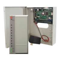
4.7.1 Direct Power Supply
Connect the power supply to the POWER 7-pin pluggable screw connector. Refer to
Connecting Diagrams, page 102 for a complete diagram.
Figure4.24: Location of the power supply connector
Figure4.25: Location of the power supply connector
Connect an external power supply (10 - 30 Vdc) for AMC2-4R4 at pin 1 (positive) and pin 3 (0
V) of the pluggable screw connector.
 Loading...