DICENTIS System installation overview | en 11
Bosch Security Systems B.V.
Hardware Installation Manual
2021.01 | V2.2 |
8. System Network Cable (DCNM‑CBxxx):
– Connects DICENTIS devices, the Audio processor and powering switch, and one or
more Powering switches to each other.
9. Multimedia device (DCNM-MMD / DCNM-MMD2)
– This device is used for “system power on/off”. It is always connected to the powered
socket of the Audio processor and powering switch or Powering switch.
Note: Only one DICENTIS Multimedia device should be connected here.
10. Multimedia device (DCNM-MMD / DCNM-MMD2)
– This device is used via a “Power over Ethernet” (PoE) Ethernet switch.
Note: Only one DICENTIS device should be connected here.
Participants can use their DICENTIS Discussion device to contribute to a meeting: DCNM-D,
DCNM-DVT, DCNM-DSL, DCNM-DE.
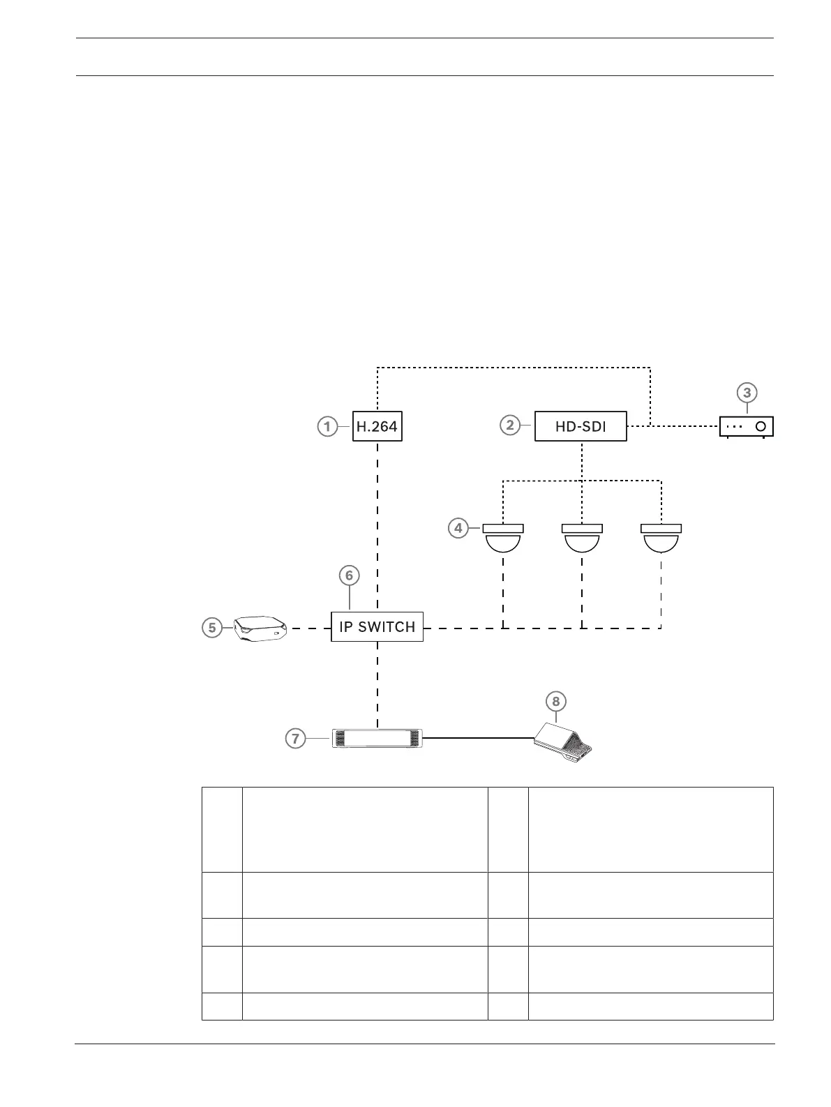
A typical camera setup in a DICENTIS Conference System consists of:
Figure3.2: Typical camera setup
1 H.264 encoder to encode the HD SDI
video to H.264 if the video camera is
not able to supply the supported
H.264 stream
2 HD-SDI switcher to switch the HD-SDI
streams of the cameras
3 Projector to show the active speaker
on the large screen
4 Video camera (Onvif Profile-S
compatible camera, Sony, Panasonic)
5 DCNM-SERVER 6 L3 Ethernet switch
7 DCNM-APS2 8 DCNM-MMD2, displaying the active
speaker on the device
….. HD-SDI (coax cable) ----- Ethernet TCP/IP