DICENTIS Table of contents | en 3
Bosch Security Systems B.V.
Hardware Installation Manual
2021.01 | V2.2 |
Table of contents
1
Safety 4
2
About this manual 6
2.1 Intended audience 6
2.2 Alerts and notice signs 6
2.3 Copyright and disclaimer 6
2.4 Document history 6
3
System installation overview 9
3.1 Typical system setup 10
3.2 System extension 13
4
System installation design and planning 17
4.1 System capabilities 17
4.2 Hardware requirements 19
4.3 Power supply capacity calculation plan 22
4.3.1 Calculation using DCNM-APS2 or DCNM-PS2 22
4.3.2 Calculation using PoE switches 25
4.4 Redundancy options 28
4.4.1 Redundant cabling for DCNM-APS2/DCNM-PS2 units 29
4.4.2 Redundant server PC 31
5
Installation material and tools 32
5.1 DCNM-CBCPLR Cable couplers 32
5.1.1 Using a cable coupler to extend a cable 33
5.1.2 Using a cable coupler as a break-out box 33
5.1.3 Using a cable coupler as an interface between different types of cable 34
5.1.4 Using a cable coupler to insert power locally 35
5.1.5 Using a cable coupler to switch the system on 36
5.2 DICENTIS System Cable Assemblies 38
5.3 DCNM-CBCON Connectors for DICENTIS cable 40
5.4 DCNM-CBTK System Network Cable Toolkit 41
5.5 DCNM-CB250-I System Installation Cable 42
5.6 DCNM-IDESKINT On-air & teleph. DCNM-IDESK 43
6
Mechanical installation of Central Equipment 47
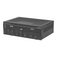
6.1 Audio processor and powering switch and Powering switch 47
6.2 System server 51
6.3 Dante gateway 52
7
Mechanical installation of Contribution Devices 56
7.1 DICENTIS tabletop devices 56
7.2 DICENTIS flush-mounted devices 61
7.2.1 DCNM-FSL Flush language selector 66
7.3 DCNM-IDESK / DCNM-IDESKVID Interpreter desk 69
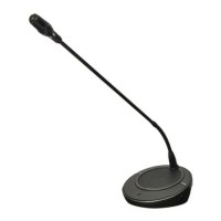
7.4 DICENTIS Microphones 72
7.5 DCNM-MMDSP Anti-reflection foil 74
7.6 DCNM-NCH Name Card Holder 75
8
Installation Test 76