10 en | System installation overview DICENTIS
2021.01 | V2.2 |
Hardware Installation Manual
Bosch Security Systems B.V.
3.1 Typical system setup
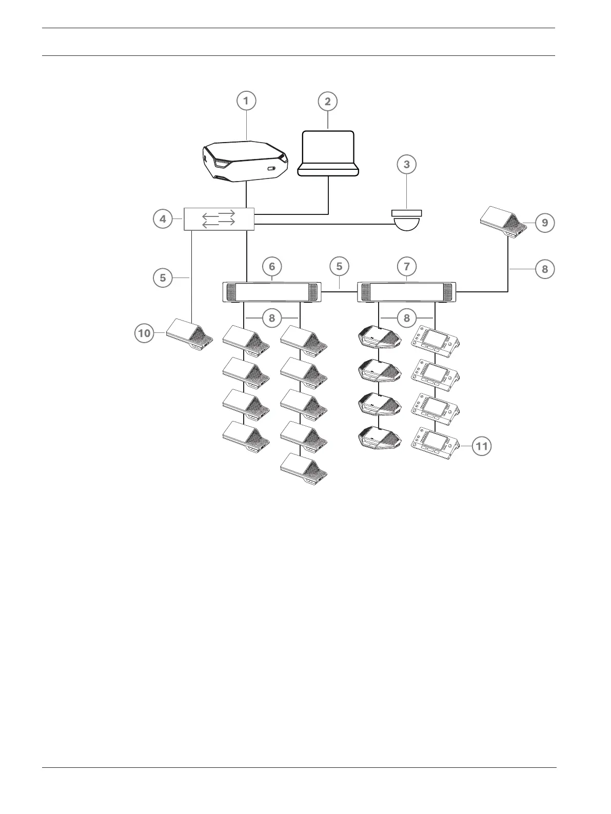
Figure3.1: Typical DICENTIS Conference System setup
A typical DICENTIS Conference System consists of:
1. System server (DCNM-SERVER):
– The heart of the system. It licenses functionality, configures and controls the system.
2. Client PC:
– Can be used to: Manage meetings, prepare meetings and configure the system.
3. Optional video camera (Onvif Profile-S compatible cameras, Sony IP cameras via CGI
commands, or Panasonic HD Integrated IP) + external power supply:
– Captures the image of a speaking participant.
4. Ethernet switch:
– Ethernet switch with PoE on some ports.
- Routes the system data via Ethernet.
- Provides power to the DICENTIS devices via PoE.
5. CAT‑5e Ethernet cable (minimum requirement).
6. Powering switch (DCNM-PS2):
– Is used to increase the number of DICENTIS devices connected to the system.
7. Audio processor and powering switch (DCNM-APS2):
– Controls the system audio, routes audio from and to the system and supplies power
to the DICENTIS devices.