38 en | Installation material and tools DICENTIS
2021.01 | V2.2 |
Hardware Installation Manual
Bosch Security Systems B.V.
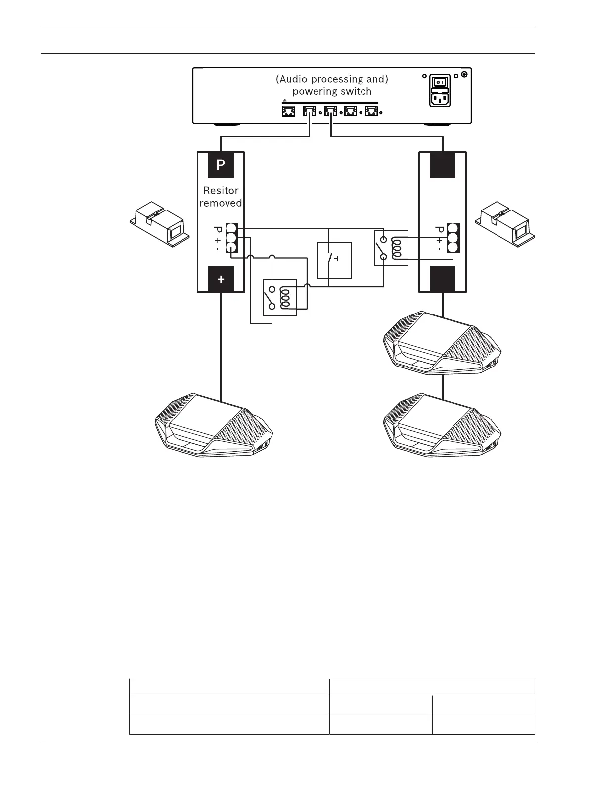
Figure5.8: Using cable couplers and custom made switch to create a wake-up switch
The schematic works as follows:
1. By pressing S1 (pulse switch), the device connected to the always powered output
receives power and powers up.
2. The device powers up and is discovered by the services. When a device is discovered, the
3.0A outputs of the (A)PS are enabled and any devices connected to these outputs are
also powered up.
3. Relay R1 has a timer of 1 minute, so the switch will stay closed for 1 minute after
releasing switch S1 or powering down the system.
4. When the high power trunks are powered up, the switch of relay R2 will power relay 1 to
keep the switch closed.
5.2 DICENTIS System Cable Assemblies
The DICENTIS System Cable Assemblies, terminated with connectors on both ends, are
available in different lengths and are used to connect DICENTIS devices to each other. The
cable consists of a low smoke zero halogen solid core.
Ordering number Cable lengths
m ft
DCNM-CB02-I 2 6.56