24 en | System installation design and planning DICENTIS
2021.01 | V2.2 |
Hardware Installation Manual
Bosch Security Systems B.V.
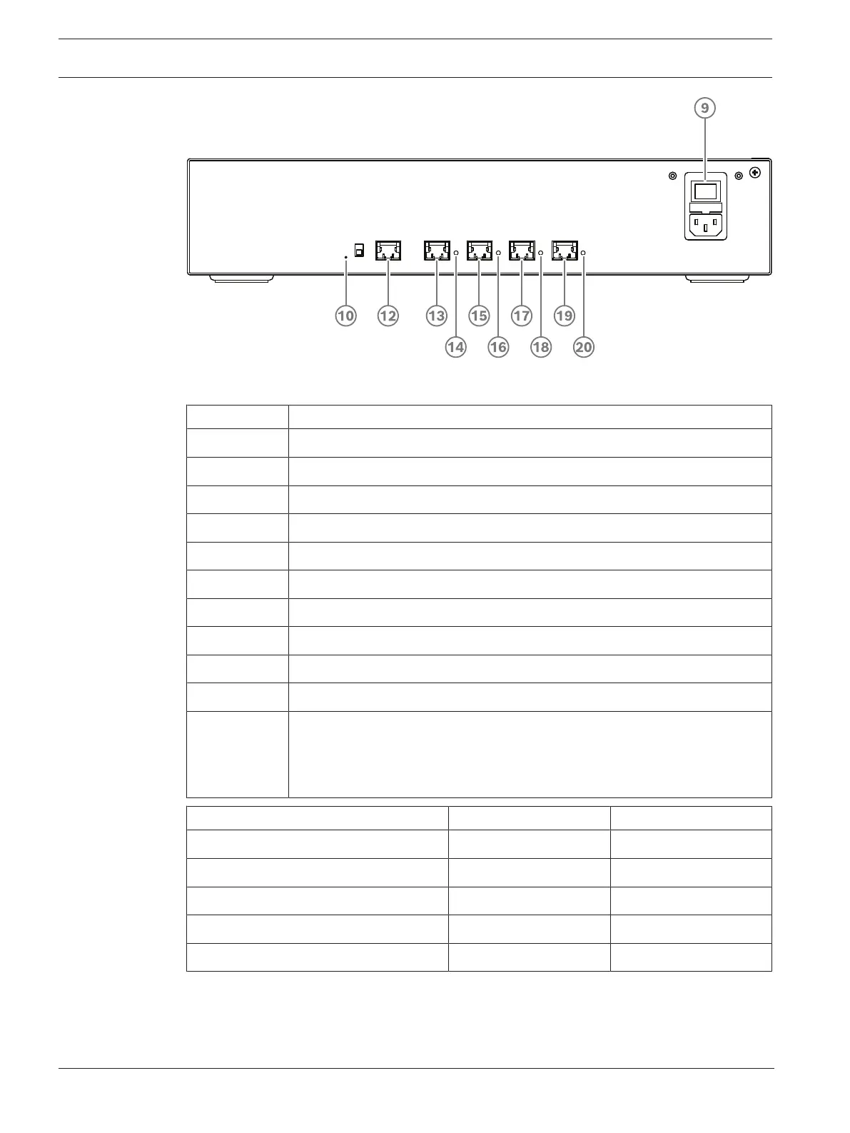
Figure4.3: Powering switch
Item Description
1, 5 XLR line outputs 1 and 2.
2, 6 RCA line outputs 1 and 2.
3, 7 XLR line inputs 1 and 2.
4, 8 RCA line inputs 1 and 2.
9 Mains inlet, mains switch and fuse holder.
10 Reset button.
11 Ground switch (grounded or floating).
12 Socket 1 without power.
13 Socket 2 low power.
15, 17, 19 Socket 3, 4, 5 high power.
14, 16, 18, 20 Overload LED for sockets 2‑5:
Green: Power OK.
Red: Overload. Remove cable and wait a few seconds for the system to
reset the overload.
Network and Power connector Max. power output (W) Max. devices
Socket 1 (12) No power capacity ---
Socket 2 (13) 15 1
Socket 3 (15) 144 40
Socket 4 (17) 144 40
Socket 5 (19) 144 40
Tab.4.5: Power supply capacity DCNM‑APS2 / DCNM‑PS2