16 en | System overview DIVAR IP all-in-one 6000
2022-10 | V02 | F.01U.407.903
Installation manual
Bosch Security Systems B.V.
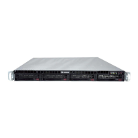
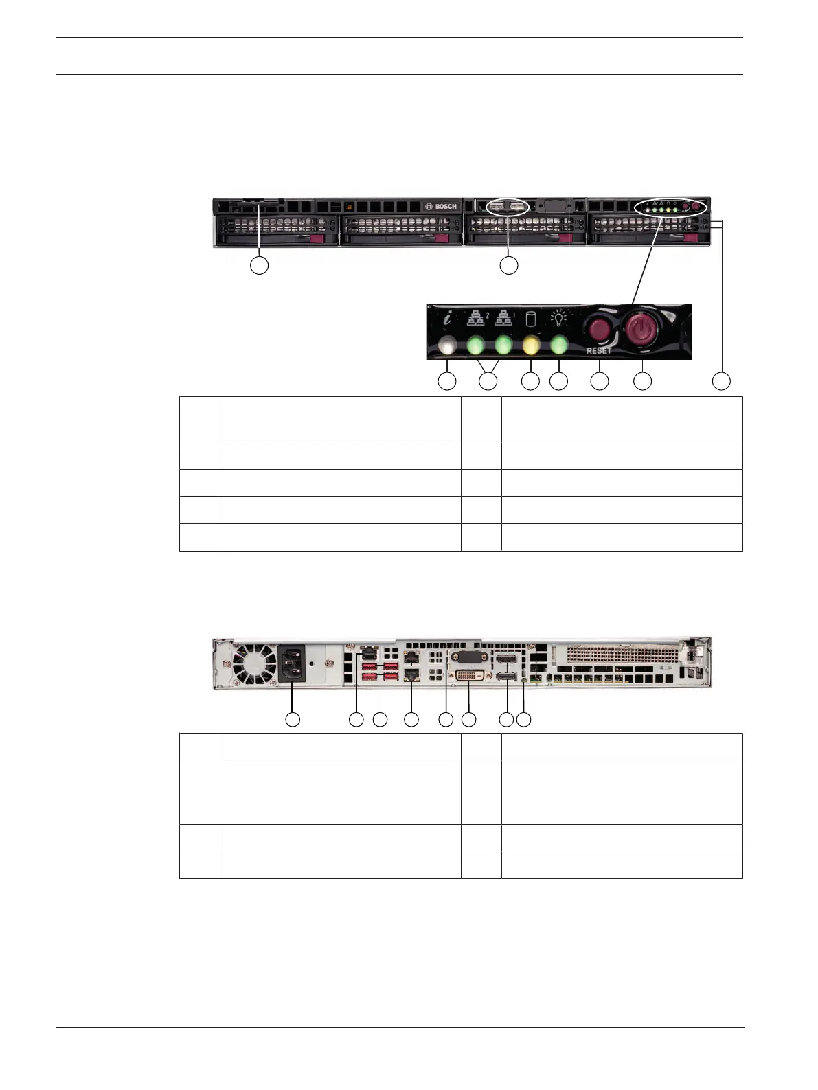
3.1 Device views
Front view
1 Information tag with device
identification data
2 2 USB2.0 ports (Type A)
3 Information LED 4 NIC1 and NIC2 LEDs
5 HDD LED (not used) 6 Power LED
7 Reset button 8 Power button
9 Hard drive carrier LEDs
Rear view
1 Mains connection 2 IPMI port
3 4 USB ports 3.2 (Type A) 4 2 LAN ports (RJ45), teamed
Note: Do not change the teaming
mode!
5 VGA display output (disabled) 6 DVI-D port
7 2 DisplayPort ports 8 UID LED
3.2 Control panel elements
The control panel located on the front of the device has power buttons and status monitoring
LEDs.
 Loading...