1 689 989 115 2013-08-30| Robert Bosch GmbH
20 | FSA 500 | Symbols useden
Disposal
Dispose of used electrical and electronic
devices, including cables, accessories and
batteries, separately from household waste.
1. Symbols used
1.1 In the documentation
1.1.1 Warning notices - Structure and meaning
Warning notices warn of dangers to the user or people in
the vicinity. Warning notices also indicate the consequenc-
es of the hazard as well as preventive action. Warning no-
tices have the following structure:
Warning
symbol
KEY WORD – Nature and source of hazard!
Consequences of hazard in the event of fail-
ure to observe action and information given.
¶ Hazard prevention action and information.
The key word indicates the likelihood of occurrence and
the severity of the hazard in the event of non-observance:
Key word Probability of
occurrence
Severity of danger if in-
structions not observed
DANGER Immediate impend-
ing danger
Death or severe injury
WARNING Possible impending
danger
Death or severe injury
CAUTION Possible dangerous
situation
Minor injury
1.1.2 Symbols in this documentation
Symbol Designation Explanation
!
Attention Warns about possible property damage.
i
Information Practical hints and other
useful information.
1.
2.
Multi-step
operation
Instruction consisting of several steps.
e
One-step
operation
Instruction consisting of one step.
Intermediate
result
An instruction produces a visible inter-
mediate result.
"
Final result There is a visible final result on com-
pletion of the instruction.
1.2 On the product
! Observe all warning notices on products and ensure
they remain legible.
Attention is to be paid to these operating instructions
as well as all the technical documentation for the tester
and the components used.
DANGER – Risk of electric shock from ex-
cessively high measurement voltage.
The measurement of voltages in excess of
60VDC/30VAC/42VACpeak using Multi
measurement leads CH1/CH2 will result in
injury, heart failure or fatal electric shocks.
¶ Never use Multi measurement leads CH1 /
CH2 to measure mains or similar voltages.
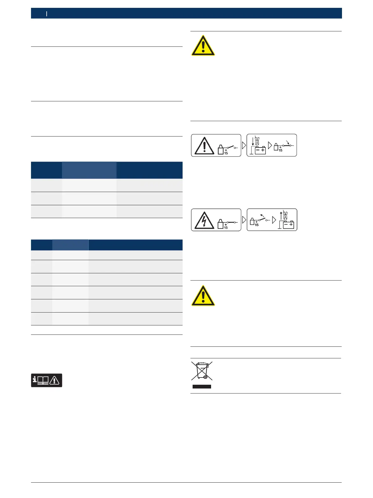
Caution!
1. Switch off the ignition.
2. Connect the FSA 500 to the battery (B–) or engine
ground.
3. Switch on the ignition.
Caution!
1. Switch off the ignition.
2. Disconnect the FSA 500 from the battery (B–) or engine
ground.
DANGER – Risk of electric shock if measure-
ments are taken on motor vehicles without
connecting cable B–!
Measurements taken with connecting cable
B– not connected to vehicle ground or the
negative post of the battery will result in in-
jury, heart failure or fatal electric shocks.
¶ Connect the FSA 500 by way of connect-
ing cable B – to vehicle ground or the
negative post of the battery.
¶ Heed the following connection sequence.

 Loading...