1 689 989 115 2013-08-30| Robert Bosch GmbH
Product description | FSA 500 | 25 en
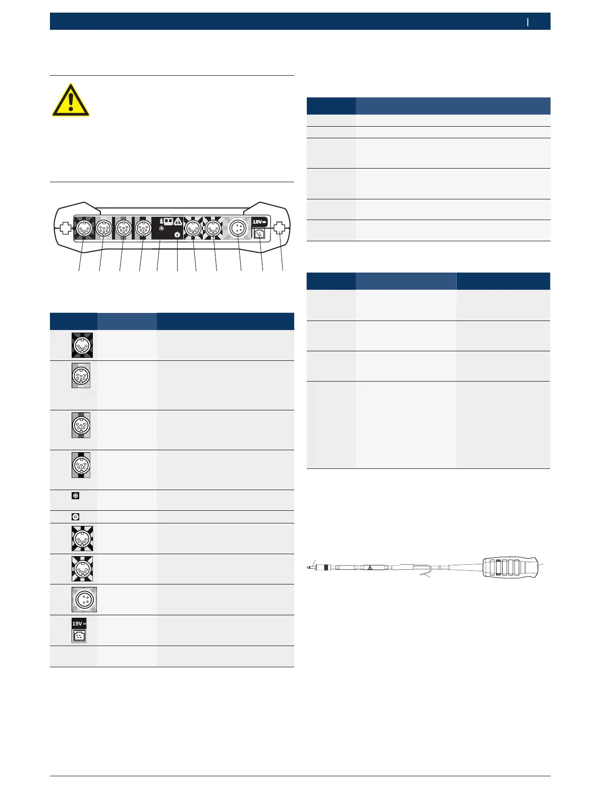
3.5.3 FSA 500 connection panel
DANGER – Risk of electric shock from
excessively high measurement voltage.
The measurement of voltages in excess of
60VDC/30VAC/42VACpeak using Multi
measurement leads CH1/CH2 will result in
injury, heart failure or fatal electric shocks.
¶ Never use Multi measurement leads CH1 /
CH2 to measure mains or similar voltages.
6
Fig. 2: FSA 500 connection panel (viewed from underneath)
Item Color code Connection
2)
1 Red/black Connecting cable B+/B–
(connecting cable B– for vehicle
ground)
2 Green or
white or yel-
low
Secondary measuring transduc-
er or current probe 30 A or cur-
rent probe 1000 A or adapter cable
1681032098 with fluid pressure
sensor (both special accessories)
3 Green or red
or yellow
Multi measurement lead CH2 or
measurement lead with voltage di-
vider or current probe 30 A or cur-
rent probe 1000 A
4 Green or blue
or yellow
Multi measurement lead CH1 or
measurement lead with voltage di-
vider or current probe 30 A or cur-
rent probe 1000 A
5 - Coupling with hose (atmospheric
pressure measurement)
6 - Remote trigger
7 White/black Clip-on trigger or adapter cable
1 684 465 513 for clip-on sensor
1)
8 Blue/white Oil temperature sensor, air and IR
temperature sensor (special acces-
sories)
9 Yellow/green Primary connecting cable (UNI 2)
10 - Power supply unit connection
11 - - Connection for charging station
(special accessory)
1)
For speed measurements with a clip-on sensor, the adapter
cable 1 684 465 513 must always be connected between the
FSA 500 socket (Pos.7) and the connecting cables for the
clip-on sensor.
2)
The color codings on the connection cables refer to the correct
connection at the FSA 500.
3.5.4 LED displays
LED A: Status indicator
Status LED A
Not lit FSA 500 off.
Red light FSA 500 starting.
Flashing
white
(1 Hz)
FSA 500 on, but not yet ready for operation.
No data link with PC/Laptop.
Flashing
green
(1 Hz)
FSA 500 ready for operation.
Data link to PC/Laptop established via USB.
Flashing
blue (1 Hz)
FSA 500 ready for operation.
Data link to PC/Laptop established via Bluetooth.
Flashing
red (4 Hz)
Firmware error.
FSA 500 not ready for use.
LED B: Charge indicator
Status LED B Action
Not lit No external power
supply connected.
Power supply via battery.
-
Violet light External power supply
connected. Battery being
charged.
-
Blue light External power supply
connected. Battery is
charged.
External power supply
can be disconnected.
Red light External power supply
connected.
Possible cause of
trouble:
R Battery temperature
> 45 °C
R Battery not connected
R Battery defective
R Connector defective
Check battery and
connector.
Allow the FSA 500 to
cool down.
3.5.5 Remote trigger
The start soft key (F3) or the stop soft key (F4) in the
FSA 500 CompacSoft [plus] software can be activated
with the button on the remote trigger.
1
2
1 684 463 828
BOSCH
30V
459903-041_Ko
Fig. 3: Remote trigger (1 684 463 828)
1 Button
2 Strain relief
3 Connector for FSA 500
i For connection refer to Fig. 2, Pos. 6.
 Loading...