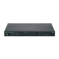
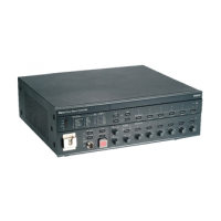
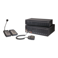
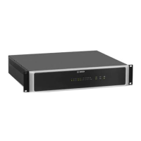
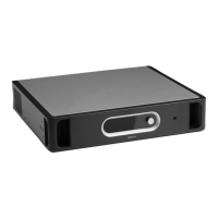
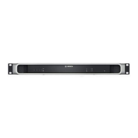
Plena Voice Alarm Router
0 dB
-6dB
-20dB
B
Processor reset
Network
Call/EMG
Music/Spare
Ground short
Input
Mains
Battery
Zone1
Zone2
Zone3
Zone4
Zone5
Zone6
Alarm
Zone select
A
Fault Indicators
Zone select
Zone1 Zone2 Zone3 Zone4 Zone5 Zone6
10k
10k
Booster 1 in
Override/Trigger Output
Trigger Input
Business
Emergency
Firmware upgrade
Firmware Upgrade
LBB 1992/00 8900 199 20001
Plena Voice Alarm
Router
115-230V~,50
/60Hz
S/N.
Design & Quality
The Netherlands
N663
Termination
100V 0 100V 0 100V 0 100V 0 100V 0 100V 0 100V 70V 0 100V
Z1 Z2 Z3 Z4 Z5 Z6
Booster 1
Out
1...9
ID
Router
Rated input power
:100VA
Line fuse:T1L250V for 230V AC
T2L250V for 1
15V AC
Warning
This apparatus must be earthde
TRG1 TR G2
1 2 3 4 5 6
COM
NC
NO
1 2 3 4 5 6
1 2 3 4 5 6
1 2 3 4 5 6
Z1 Z2
Z3
Z4
Z5
Booster
Failure
GND
Booster 2
Z6
24V
DC Out
TRG1 TRG2
Booster
Failure
24V
DC Out
A
1
00V 0 100V 0 100V 0 100V 0 10
0V 0 100V 0 100V 0 +24V-
Booster 2 in
Z1 Z2 Z3 Z4 Z5 Z6
B
DC In
Z1
Z2
Z3
Z4
Z5
Z6
24V
1 Channel 2 Channel
Booster 1
Booster 2
BGM/ Spare
N.C./Spare
Call
BGM/ Call
V.O.R.
V.O.R.
NC
NO
24V
In
Out
Pow er
Appara tu s
delive re d
Co nn ec ted
for 23 0V ~
115V~
230V ~
Call out
Made in China
Off
On
1
76
2 3
4
5 9 10 118 12
1314151617
1819
2024
21
22
23
Figure 3.4: Front and rear views of the voice alarm router
Controls, indicators and connectors on the voice alarm router:
1. Power LED/VU Meter:
A combined power indicator and VU meter. The green power LED is lit if the voice alarm
router is connected to the mains or back-up power and switched on. The VU meter
indicates the master VU level: 0 dB (red), -6 dB, -20 dB (yellow).
2. Fault indicators:
Eight yellow system fault LEDs (Processor reset, Network, Call/EMG, Music/Spare,
Ground short, Input, Mains, Battery) and twelve yellow loudspeaker line fault LEDs. Fault
indication is only possible if supervision is enabled (see section Fault indicators, page
98).
3. Emergency call zone selectors:
Six buttons to select the zones to which the emergency call must be distributed (see
section Emergency state, page 91). Each button has a green and a red LED. The six red
LEDs indicate the zones that are selected for the emergency call. The six green LEDs
indicate the zones in which a business call is running.
4. BGM zone selectors:
Six buttons to select the zones to which the BGM is distributed (see section Background
music, page 88). Each button has a green LED. The six green LEDs indicate the zones to
which BGM is distributed.
5. Zone outputs:
Six zone outputs to connect loudspeakers to the voice alarm router. Each zone output
consists of two loudspeaker line outputs (see section Loudspeakers, page 66).
3.3.5
Plena System overview | en 19
Bosch Security Systems B.V. Installation and Operation manual 2013.07 | V2.0 |
 Loading...


