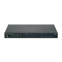
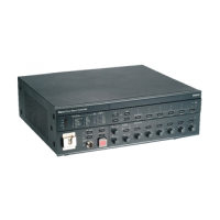
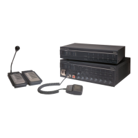
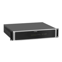
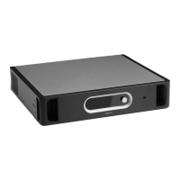
Figure 3.13: Front and rear views of the fireman’s panel
Overview of the controls, connections and indicators on the fireman’s panel:
1. Power LED/VU Meter:
A combined power indicator and VU meter. The green power LED is lit if the fireman’s
panel is connected to the power supply. The VU meter indicates the call level: 0 dB (red),
-6 dB, -20 dB (yellow).
2. Emergency button:
A push button to put the system in the emergency state (see section Emergency state,
page 91).
3. Emergency acknowledge:
A push button to acknowledge the emergency state (see section Emergency state, page
91).
4. Emergency reset:
A push button to reset the emergency state (see section Emergency state, page 91).
5. Alarm message button:
A push button to start the default alarm message. This button is only available in the
emergency state (see section Emergency state, page 91).
6. Fault acknowledge:
A push button to acknowledge the fault state (see section Fault State, page 96).
3.10
30 en | System overview Plena
2013.07 | V2.0 | Installation and Operation manual Bosch Security Systems B.V.
 Loading...


