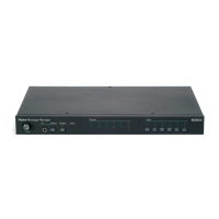
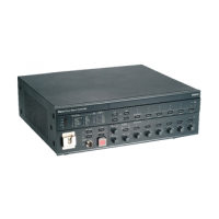
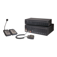
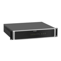
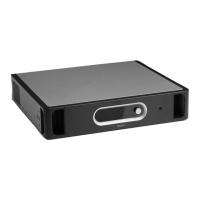
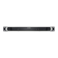
Remote Control Extension
Remote control
Connect the remote control extension to the remote control (see section Remote control
extensions, page 70).
Status output contacts
The remote control extension has 3 status output contacts to indicate the current system
state. The procedure for connecting the status outputs is the same as the procedure for
connecting status outputs to the voice alarm controller (see section Status output contacts,
page 61).
Power
Connect a back‑up power supply to the remote control extension.
The 24 V output of the Controller or the Router can be used for this. Those outputs are
powered by mains and back‑up power. It is also possible to install a floating (without ground
reference) 24 V power supply with backup battery (EN54‑4 compliant for EN54‑16 compliant
systems, or EN60849 compliant).
Figure 5.29: Connecting a power supply
Remote Control Extension Kit
Rear panel
The rear panel of the remote control extension kit has the same connectors and controls as
the rear panel of the Voice Alarm Control Extension. See section Remote Control Extension,
page 73 for connection details.
LEDs
To the LEDs/LAMPS connectors on the front panel of the remote control extension kit, the
LEDs can be connected (see Voice Alarm Remote Control kit, page 27).
Lamps
To the LEDs/LAMPS connectors on the front panel of the remote control extension kit, lamps
can be connected (see Voice Alarm Remote Control kit, page 27).
5.6
5.6.1
5.6.2
5.6.3
5.7
5.7.1
5.7.2
5.7.3
Plena Connection | en 73
Bosch Security Systems B.V. Installation and Operation manual 2013.07 | V2.0 |
 Loading...


