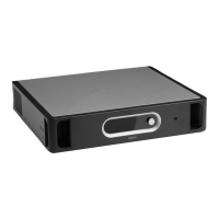
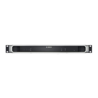
Figure 3.7: Top and bottom views of the call station
Controls, indicators and connectors on the call station:
1. Power indicator:
A green LED to indicate that the call station is powered on.
2. Zone selection buttons:
Six buttons to select the zones to which the business call is distributed (see section
Business calls, page 89). Each button has a green LED, which indicates the zones to
which the business call is distributed.
3. ‘All call’ button:
A button to select all zones (see section Business calls, page 89).
4. Push-to-talk button:
A push-to-talk (PTT) button to start the business call.
5. Status indicators:
Three LEDs that indicate the status of the call station (see section Make the
announcement, page 90).
6. Keypad connector:
A connector to connect call station keypads to the call station.
7. Configuration settings:
A set of DIP switches to configure the call station (see section Call station, page 83).
8. Power supply inlet:
A socket to connect a 24 V(DC) power supply (see section Power supply, page 69).
9. System sockets:
Two redundant RJ45 sockets to connect the call station to the voice alarm controller (see
section Call station, page 50).
3.4.4
Plena System overview | en 23
Bosch Security Systems B.V. Installation and Operation manual 2013.07 | V2.0 |
 Loading...


