Motor encoder
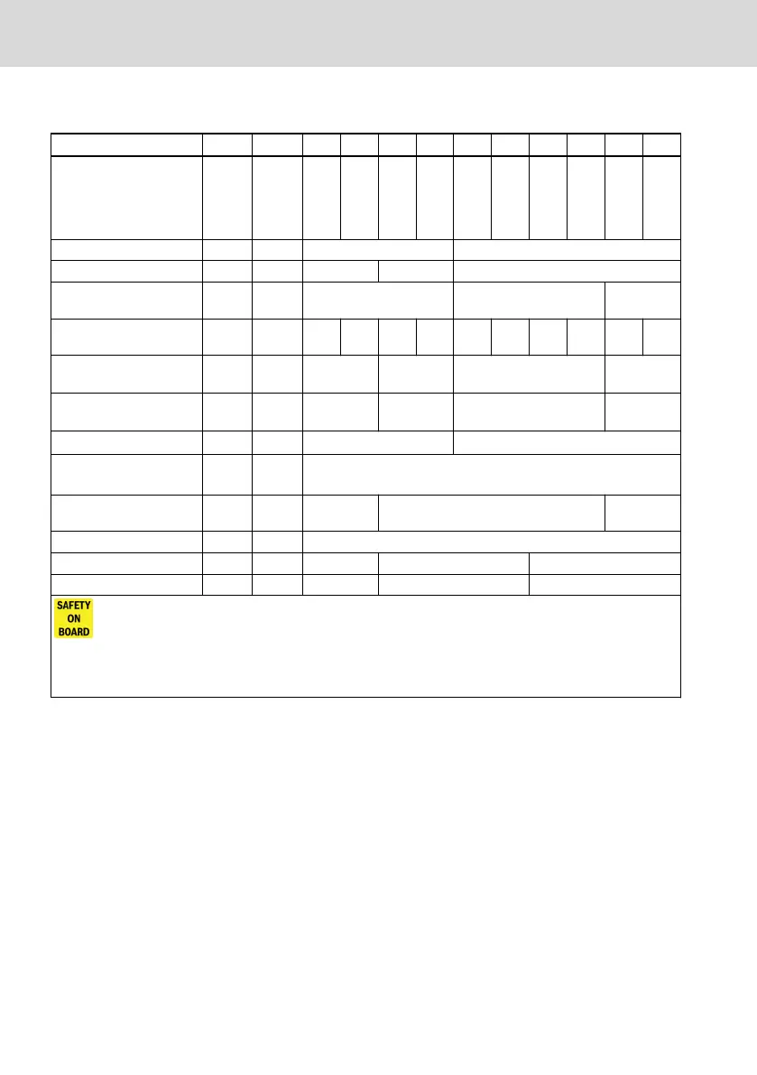
Designation Symbol Unit AM AS BM BS CM CS HM HS DM DS
Encoder design - -
Multi-
turn
abso-
lute
Sin-
gle-
turn
abso-
lute
Multi-
turn
abso-
lute
Sin-
gle-
turn
abso-
lute
Multi-
turn
abso-
lute
Sin-
gle-
turn
abso-
lute
Multi-
turn
abso-
lute
Sin-
gle-
turn
abso-
lute
Multi-
turn
abso-
lute
Sin-
gle-
turn
abso-
lute
Encoder Interface - - HIPERFACE® ACURO®link
Encoder signal periods ~/⑀ - 16 128 -
Functional encoder resolu-
tion (single-turn)
- - 20 bit 24 bit
Distinguishable revolu-
tions
U
turn
- 4096 1 4096 1 4096 1 4096 1 4096 1
System accuracy of en-
coder
1
∢ '' ±520 ±120 ± 36 ± 20
System accuracy typical/
maximum
2)
∢ ''
±360 /
± 520
±120 ±50 / ± 70 ±20 / ± 30
Encoder output signal
V
out
1Vss -
Encoder voltage supply
VCC
En-
coder
V 7...12
Encoder max. current con-
sumption
I
Encoder
mA 50 60 130
Functional safety
Safety integrity level - - SIL 2 SIL 3
Performance level - - Category 3, PL d Category 3, PL e
For more information about Integrated Safety technology and the requirements to use motors with encoder sys-
tems for Safety technology applications with IndraDrive, see IndraDrive Integrated Safety Technology “Safe Motion”
DOK-INDRV*-SI3*SMO-VRS-APxx-xx-P.
1) The installation mechanics can sporadically influence the accuracy of the overall system.
2) Reachable overall system accuracy by taking the installation mechanics into considera-
tion, typical and maximum value.
Tab. 4-5: Technical data of encoder
20/101
About this product
MS2N Synchronous Servomotors
Bosch Rexroth AG R911347581_Edition 04