3-4 Description REFUspeed RS51
DOK-RD500*-RS51*******-IB02-EN-P
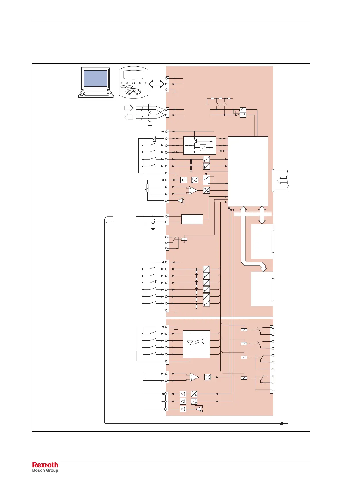
3.4 Circuit principle
REFU
win
Output +24 V
Sparking
Sensitivity /
load limit
Optional control terminal strip T1
TEST
Analog output 1
Analog output 2
Analog ground
f
min
Int. setpoint 2
0
Int. setpoint 2
1
Para-Set 2
4
Analog input +
Analog Input -
Analog ground
Analog out/ref.
Fault signal
Fault
acknowledgment
Output +15 V
Parameter set
selection 1-32,
binary-coded
X34 analog input
Temperatur
evaluation
Operator panel,
REFUwin
Ser. communications
via USS Protocol
(RS485)
Auxiliary power supply
Bidirectional digital inputs
and digit5al outputs
Analog output / reference
Analog input
Temperature sensor
Relay output
Digital inputs
Digital inputs
Analog inputs
Analog outputs
From the control
computer
To the next
bus node
Dig. ground
PTC/KTY84+
PTC/KTY84-
2
1
2
2
2
0
X11 interface (RS232)
2
3
5
T x D
R x D
X12 interface (RS485)
1
2
T x D + / R x D +
T x D - / R x D -
X14 standard terminal strip
1
2
3
4
5
6
7
8
9
10
11
X15 temperature sensor
1
2
X16 relay output
1
2
3
X17 Digital inputs
P15V
1
2
3
4
5
6
7
8
X31 digital inputs
1
2
3
4
5
6
1
2
X33 analog outputs
1
2
3
24V
5V
5V
5V
5V
5V
5V
Control card
Bus termination
+5 V
S1
P24 V
Output
Input
24V
5V
24V
5V
24V
5V
+10 V
-10 V
Analog out.
Microprozessor
Process data interface
SS4 SS2
Module slot 1
Module slot 2
X32 relay outputs
1
2
3
4
5
6
7
8
9
10
REFU
Esc Mon
Prog
Enter
Start
Stop
ALM sensitivity up
On
Stop
2
3
ALM sensitivity down
24V
24V
24V
24V
24V
Fig. 3-2: Circuit principle, electronics section
LSA Control S.L. www.lsa-control.com comercial@lsa-control.com (+34) 960 62 43 01