3-6 Description REFUspeed RS51
DOK-RD500*-RS51*******-IB02-EN-P
BW
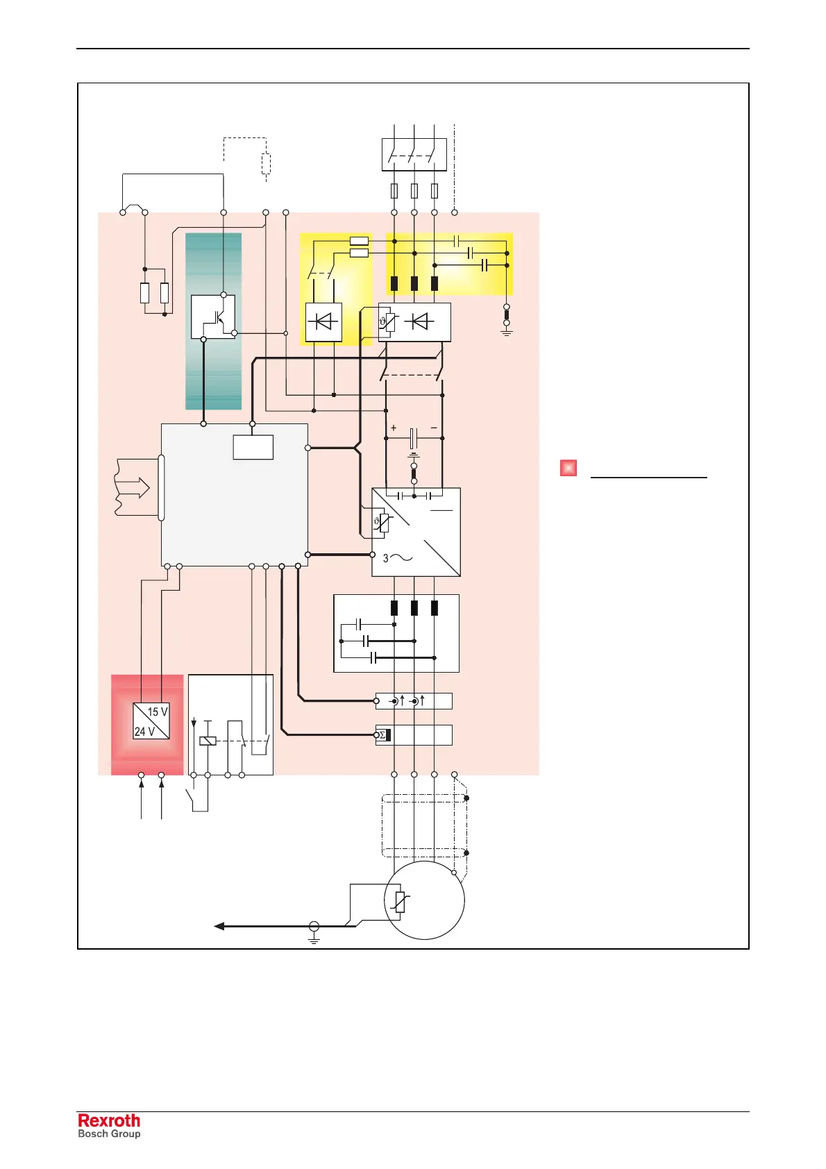
Supplementary function
EW Ground fault PT
Gl Rectifier
K1 Main contactor
K2 Pre-charging relay
NF Line filter
SE Current sensing
SNT Switched-mode power
supply
VL Pre-charging
WS Inverter control
WR Inverter
SF Sinusoidal filter
X80 Start inhibit
BC Braking chopper
BW Brake resistor
X83 Electronic standby
supply
Line supply connection
3 phases
L1 L2 L2 PE
Ext. line contactor
Ext. fuses
FF
C
D
X1
U1 V1 W1 PE
K1
K2
VL
NF
BC
GL
GL
X161
Internal
brake resistor
SNT
WS
WR
SF
SE
EW
Inverter control
X155
DC link
U2 V2 W2 PE
Start inhibit
+24 V
1 2
3 4
X80X83
Standby
1 2
+24 V Ground
Electronics
Standby
Supply
M 3 ~
J
Circuit principle
Electronics section
X1
X2
B
When using an external brake
resistor, the jumper between
X1 B nad X1 F must be
removed.
Fig. 3-4: Circuit principle, power section GK L and M
LSA Control S.L. www.lsa-control.com comercial@lsa-control.com (+34) 960 62 43 01