Disassembly / Assembly
Infusomat® Space 6.0 3 - 37EN
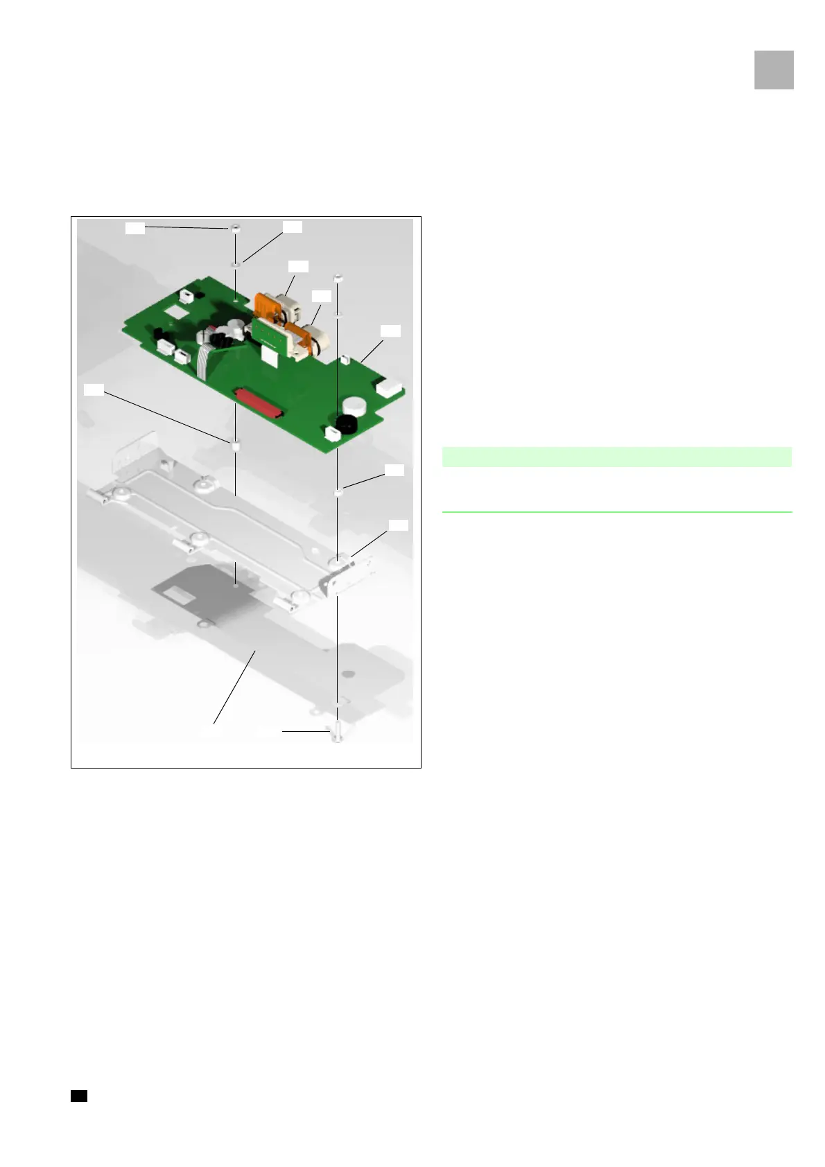
3.13 Processor PCB
Designation Order No.
Processor PCB ISP . . . . . . . . . . . . . . . . . . . . . . . . . . . . . 3452 1348
(incl. connectors)
Connector P2 . . . . . . . . . . . . . . . . . . . . . . . . . . . . . . . . . 3477 4355
Connector P3 . . . . . . . . . . . . . . . . . . . . . . . . . . . . . . . . . 3477 4359
Connector seal P2 and P3 SP (inside). . . . . . . . . . . . . . 3477 4357
Bottom inner frame ISP . . . . . . . . . . . . . . . . . . . . . . . . 3452 1453
EMC plate ISP . . . . . . . . . . . . . . . . . . . . . . . . . . . . . . . . 3452 1440
Rating plate ISP . . . . . . . . . . . . . . . . . . . . . . . . . . . . . . . On request
Screws
(see „Service Parts and Screw Kit“ ➨ pg. 3 - 7)
Please pay attention to the corresponding notes during assembly
and installation (see „Processor PCB“ ➨ pg. 3 - 41).
Disassembly
1. Loosen two hexagon nuts (Fi
g.: 3 - 38 / Item 1) and remove
the nuts with the toothed locked washers (Fig.: 3 - 38 /
Item 2), the distance sleeve (Fig.: 3 - 38 / Item 10) and the
countersunk screw.
2. Remove the processor PCB (Fig.: 3 - 38 / Item 5) from the
bottom inner frame.
3. Loosen one hexagon nut and rem
ove the nut together with
the EMC shield (Fig
.: 3 - 38 / Item 8) and the screw (Fig.: 3 -
38 / Item 7) from the bottom inner frame (Fig
.: 3 - 38 /
Item 6) .
Fig.: 3 - 38
Legend of fig. 3 - 38:
Item Designation
1 Hexagon nut M3
2 Toothed locked washer M3
3 Connector P2
4 Connector P3
5 Processor PCB
6 Bottom inner frame
7 Fillister head screw M3x10
8 EMC plate
9 Countersunk screw M3x12 A2 TORX (not depicted)
10 Distance sleeve

 Loading...