9-3
Be sure pilot burner gas
supply line is fully
installed into gas valve fitting during
installation. If not, a gas leak may be the
result.
10. Install in reverse order. Use gas pipe
sealer on pipe threads. Check all gas
connections and pipes with a soap
and water solution. Bubbles indicate a
gas leak.
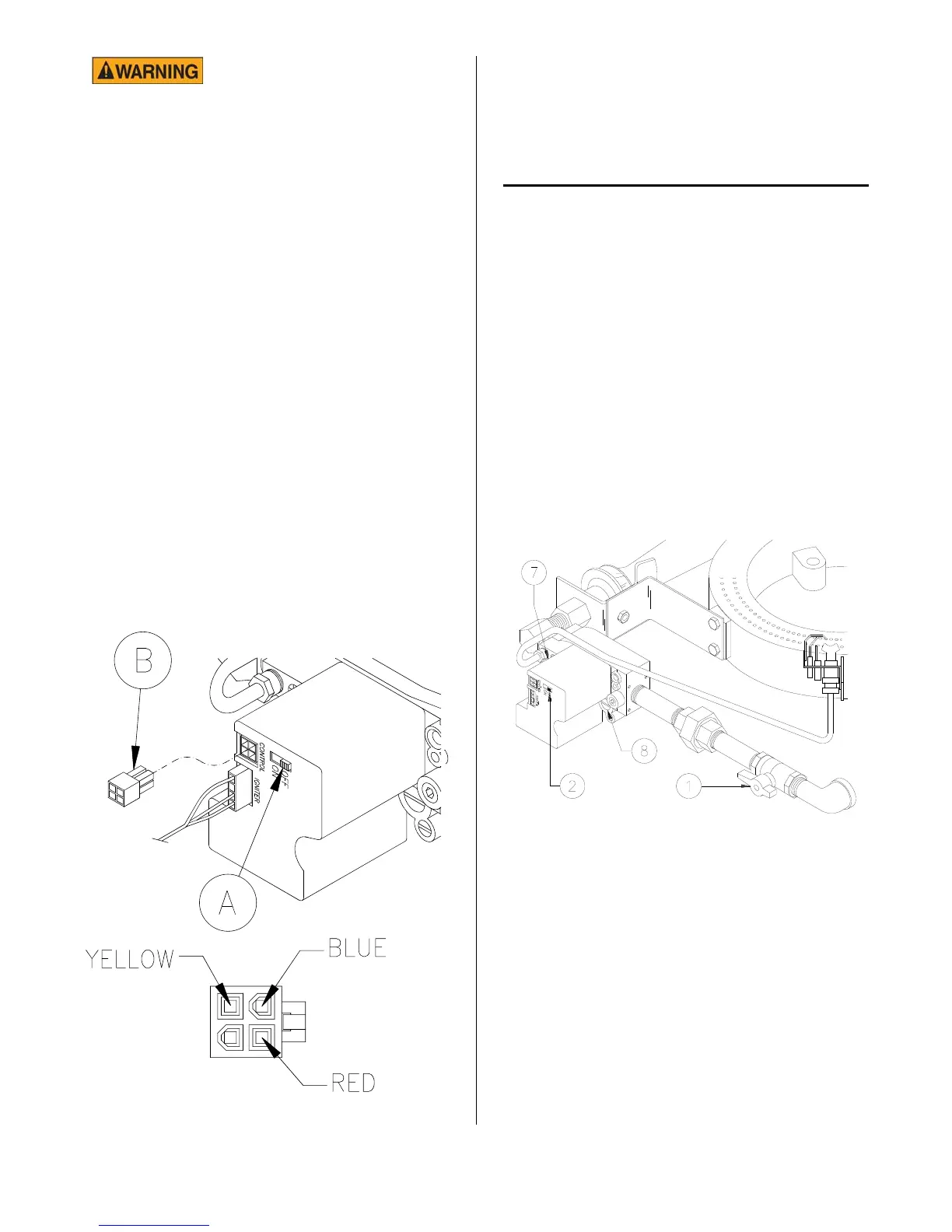
GAS VALVE POWER CHECK
1. Turn SWITCH A to off.
2. Pull out plug B.
3. Turn the COOK/FILTER switch to
COOK.
4. At the end of the plug, check for
24VAC between the blue and red wire
and the blue and yellow wire. (see
below)
5. Refer to the TROUBLESHOOTING
FLOW CHART on page 11-10 if there
is no voltage at either or both places.
FLAME ADJUSTMENTS
Gas Pressure Adjustment:
Always check gas pressure after a new gas
valve installation. Check pressure when
other gas equipment is also operating. This
will ensure adequate pressure during peak
operating times.
There is a pressure tap in output side of the
gas valve for manometer hook-up. Correct
output gas pressures, in Water Column, are:
Natural Gas: 3.5” W.C.
Propane Gas: 10.0” W.C.
1. Turn cook/filter switch, manual gas
shut off valve (1) and switch (2) OFF.
2. Remove pressure tap (7) on gas valve.
3. Install manometer.
4. Turn gas shut off valve (1) ON.
5. Light pilot see MODEL 1800GH
LIGHTING INSTRUCTIONS. Turn gas
valve switch (2) ON.
broaster.com Manuals #14680 3/99 Rev 5/14
 Loading...