Brocade FastIron X Series Chassis Hardware Installation Guide 135
53-1001723-02
Replacing a copper or fiber optic module
6
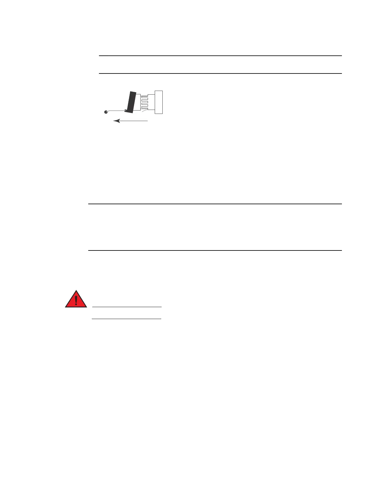
The bail latch may be attached to either the top or the bottom of the mini-GBIC.
5. Grasping the bail latch, pull the copper or fiber optic module out of the port.
6. Store the copper or fiber optic module in a safe, static-free place or in an anti-static bag.
7. Install a new copper or fiber optic module in the port. For information about performing this
task, refer to “Installing a new copper or fiber optic module”.
Installing a new copper or fiber optic module
You can install a new copper or fiber optic module (SFP or XFP transceiver) in a port while the
chassis is powered on and running.
Some older SFP modules (mini-GBICs for Gigabit Ethernet ports) have latching mechanisms which
are larger than the newer parts. These latches could interfere with one another when inserted side
by side into an interface module. Avoid using these mini-GBICs side by side in the same module.
These older modules are identified by the number PL-XPL-00-S13-22 or PL-XPL-00-L13-23 above the
Serial Number. All newer mini-GBICs do not have this limitation.
Before installing one of these modules into the port, have the following on hand:
• A new copper or fiber SFP or an XFP transceiver, all of which you can order from Brocade.
• An ESD wrist strap with a plug for connection to the ESD connector on the chassis.
For safety reasons, the ESD wrist strap should contain a series 1 meg ohm resistor.
To install a copper or fiber optic module, perform the following tasks.
1. Put on the ESD wrist strap and ground yourself by inserting the plug into the ESD connector
located in the lower right corner of the chassis front.
2. Remove the new module from its protective packaging.
3. Gently insert the copper or fiber optic module into the port until the module clicks into place.
The module is keyed to prevent incorrect insertion.
Cabling a fiber optic module
To cable a fiber optic module, perform the following tasks.

 Loading...


