Brocade FastIron X Series Chassis Hardware Installation Guide 63
53-1001723-02
Verifying proper operation
2
5. Re-attach the transparent cover that was removed in step 1.
6. Connect the wire to your DC power source making sure to connect the positive and negative
supply wires to the correct location as marked on the power supply.
7. Observe the LEDs on the power supply front panel. The DC IN and DC OUT LEDs should be
green (steady), which indicates the power supply is providing power to the chassis
components. If it is amber or OFF, the power supply is not providing power to the chassis
components. The ALM LED should be OFF.
Verifying proper operation
To verify the proper operation of the chassis after power on, you can do the following:
• Observe the LEDs
• Display the status of the modules using the CLI
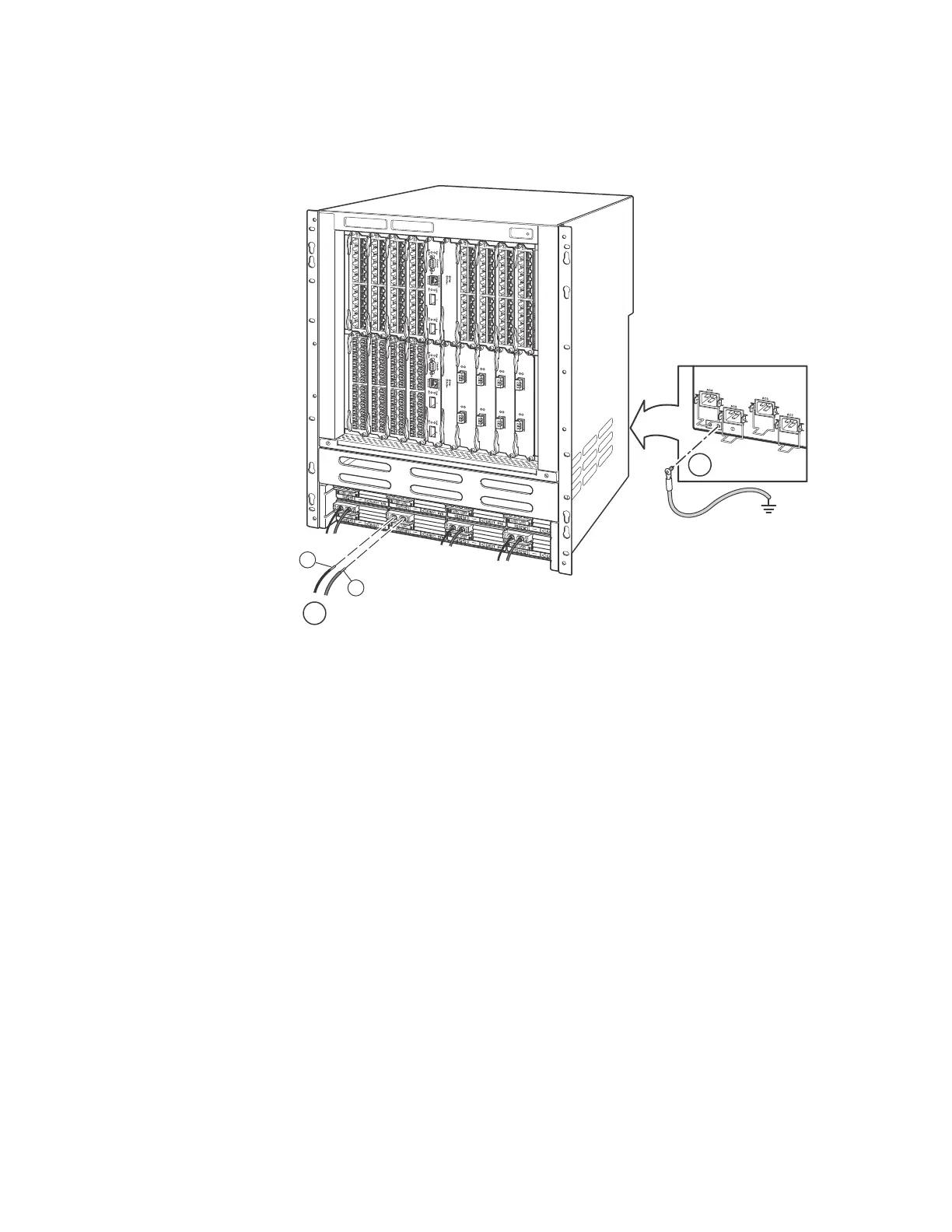
1Ground
2 DC power
+
–
1
2
Chassis
Rear View Detail

 Loading...


