Brocade FastIron X Series Chassis Hardware Installation Guide 61
53-1001723-02
Powering on the system
2
To perform this task, you need the following items:
• Flathead screwdriver
• Phillips-head screwdriver
• #6 AWG wire (grounding wire)
• #8 AWG wire (input wire)
• Crimping tool
To connect a DC power source,complete the following tasks.
1. Crimp #6 AWG ground wire and connect it to the ground position on the chassis. The ground
position is located on the side or rear of the chassis next to the ground symbol. Refer to the
illustrations in step 4.
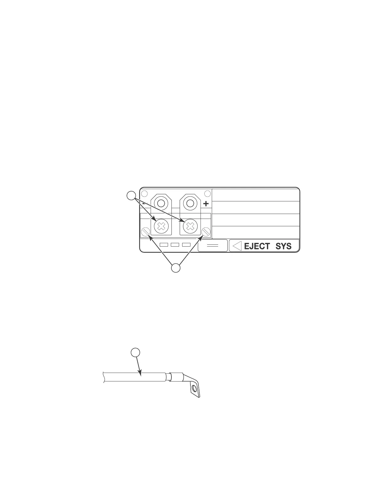
2. Use a flathead screwdriver to remove the two screws holding the transparent cover over the
power supply lugs. The following illustration shows the location of the screws and lugs.
3. Use a Phillips-head screwdriver to remove each of the power lugs.
4. Crimp #8 AWG input wire into the power lugs and reconnect the power lugs to the power supply
unit.
1 Screws holding power lugs
2 Screws holding transparent cover
1 #8 AWG power supply wire

 Loading...


