©2013 Brooks Automation Inc. Pub. No. 8040444, Rev. AA 01/14/2013 ECO No. 63723 3-15
Document Title
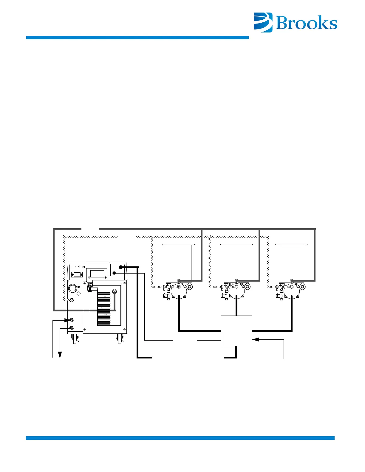
2. Connect the Cryo-Torr Power Cables between the CRYOPUMP 1,
2, or 3 connectors on the Cryo-Torr Interface and the respective
Cryo-Torr Cryopumps as shown in Figure 3-8 or Figure 3-9.
3. Connect the User Remote cable to the Cryo-Torr Interface as
shown in Figure 3-8 or Figure 3-9.
4. Connect the Remote cable between the Cryo-Torr Interface and the
Compressor as shown in Figure 3-8 or Figure 3-9.
NOTE: Your installation may vary based upon the Cryo-Torr Cryopump
models used. Refer to “Appendix A: Customer Brooks Automation
Technical Support Information” to consult your local BROOKS-
CRYOGENICS Customer Support Center for information on specific
compressor/cryopump applications.
NOTE: The Cryo-Torr Interface can be installed at the process tool
containing the cryopumps as shown in Figure 3-8 or near the Compressor
as shown in Figure 3-9. BROOKS-CRYOGENICS recommends that the
Cryo-Torr Interface be installed at the process tool to reduce cable
requirements.
Figure 3-8: Multiple Cryo-Torr Cryopump Installation
Cryopump Electrical Input
User Remote
(from vacuum system)
SUPPLY
RETURN
WATER
POWER
Remote
Cryo-Torr
Interface