and start-up
3.4 Safety installations / power limitations
3.4.1 Interlock
The interlock loop is looped through all plug-in device connections to check them for proper connection
(rectangular signal with frequency: 88 Hz ±2 Hz). The BDC546 continuously evaluates the signal from the interlock
loop. If a plug-in connection becomes loose, the BDC546 is immediately switched off. A missing change in polarity
for 9 ms. is regarded as an error.
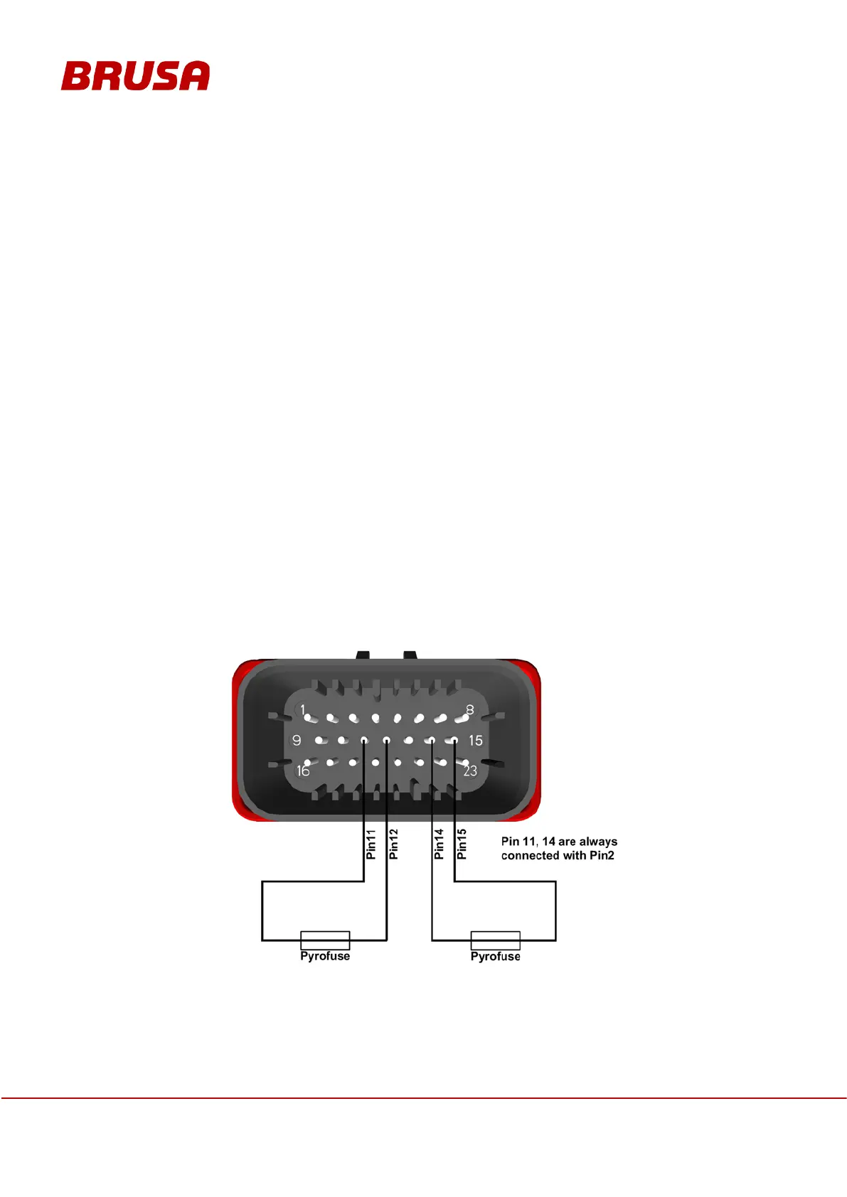
3.4.2 Pyrofuses
The BDC546 offers two digital inputs/outputs for application in a fuel cell system as follows:
To protect the fuel cell in case of an overvoltage on the lowside, a pyrofuse is provided to disconnect the
connection between the fuel cell and the BDC546. For this, a fuse with a resistance of approx. 2 Ohm can be
applied. The BDC546 offers a digital input/output each for both connection wires from the DC/DC converter to the
fuel cell. It can be connected with one pyrofuse each. The outputs are permanently supplied by the plus wiring
system/terminal 30. For a permissible LS voltage, the input has almost the same potential. In this state, a current of
approximately 20 mA flows through the fuse. This enables detection of correct wiring as well as their state (not
triggered). The signal is evaluated with a frequency of 1.5 kHz through the micro controller.
If the voltage permissible on LS is exceeded, the two inputs are set to the potential of the minus wiring
system/terminal 31. The resulting current flow ignites the pyrofuses and respectively leads to galvanic isolation of
the fuel cell from the converter.
 Loading...